NCP3063DIPINVEVB ON Semiconductor, NCP3063DIPINVEVB Datasheet - Page 14
NCP3063DIPINVEVB
Manufacturer Part Number
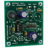
NCP3063DIPINVEVB
Description
EVAL BOARD FOR NCP3063DIPINV
Manufacturer
ON Semiconductor
Specifications of NCP3063DIPINVEVB
Design Resources
NCP3063DIPINVEVB BOM NCP3063DIPINVEVB Gerbers NCP3063 EVB Schematic
Main Purpose
DC/DC, Negative Inverter
Outputs And Type
1, Non-Isolated
Voltage - Output
-12V
Voltage - Input
4.5 ~ 6 V
Regulator Topology
Inverting
Frequency - Switching
250kHz
Board Type
Fully Populated
Utilized Ic / Part
NCP3063
Lead Free Status / RoHS Status
Lead free / RoHS Compliant
Current - Output
-
Power - Output
-
Lead Free Status / Rohs Status
Lead free / RoHS Compliant
For Use With/related Products
NCP3063DIPINV
Other names
NCP3063DIPINVEVBOS


Figure 28. NCP3063 Efficiency vs. Output Current for
100
0V
95
90
85
80
75
70
65
60
Buck External PMOS at V
330m
V
C1
0
IN
= 8 − 19 V
+
0.5
C2
100n
Figure 27. Typical Buck Application Schematic with External PMOS Transistor
OUTPUT LOAD (Adc)
1
T
V
A
V
IN
IN
= 255C
8
7
6
5
= 8 V
R3
1k
= 18 V
R2
R1
out
IC1 NCP3063
N.C.
COMP
I
V
1.5
PK
CC
= 3.3 V, f = 220 kHz,
50m
SWC
SWE
1k7
GND
TC
2
1
2
3
4
R5
1k
2.5
http://onsemi.com
C5
2n2
3
BC848CPD
T1
14
3
PMOS transistor. The principle of driving the Q2 gate is the
same as shown in Figure 27.
a pulsed feedback voltage. It is recommended to use this
pulsed feedback approach on applications with a wide input
voltage range, applications with the input voltage over
+12 V or applications with tighter specifications on output
ripple. The suitable value of resistor R6 is between
10k − 68k. The pulse feedback approach increases the
operating frequency by about 20%. It also creates more
regular switching waveforms with constant operating
frequency which results in lower output ripple voltage and
improved efficiency.
the capacitor charge and discharge currents as listed in the
electrical characteristic table, are not exceeded. Improper
selection will lead to errors in the oscillator operation. The
maximum voltage at the TC Pin cannot exceed 1.4 V when
implementing pulse feedback.
5
Figure 27 shows typical buck configuration with external
Resistor R6 connected between TC and SWE pin provides
The pulse feedback resistor value has to be selected so that
R8
470
4
2
NTGS4111P
1
6
C4
6n8
22k
R6
Q2
1N5822
D1
L1
100n
C6
10m
330m
V
C7
OUT
+
= 3V3/3 A
GND
Related parts for NCP3063DIPINVEVB
Image
Part Number
Description
Manufacturer
Datasheet
Request
R

Part Number:
Description:
1.5 A, Step−Up/Down/Inverting Switching Regulators
Manufacturer:
ONSEMI [ON Semiconductor]
Datasheet:

Part Number:
Description:
EVAL BOARD FOR NCP3063DFBSTG
Manufacturer:
ON Semiconductor
Datasheet:

Part Number:
Description:
EVAL BOARD FOR NCP3063DIPBCK
Manufacturer:
ON Semiconductor
Datasheet:

Part Number:
Description:
EVAL BOARD FOR NCP3063SMDBST
Manufacturer:
ON Semiconductor
Datasheet:

Part Number:
Description:
EVAL BOARD FOR NCP3063SMINVG
Manufacturer:
ON Semiconductor
Datasheet:

Part Number:
Description:
EVAL BOARD FOR NCP3063BSTEXG
Manufacturer:
ON Semiconductor
Datasheet:

Part Number:
Description:
ON Semiconductor [VOLTAGE REGULATOR]
Manufacturer:
ON Semiconductor
Datasheet:
Part Number:
Description:
357-036-542-201 CARDEDGE 36POS DL .156 BLK LOPRO
Manufacturer:
ON Semiconductor
Datasheet:
Part Number:
Description:
357-036-542-201 CARDEDGE 36POS DL .156 BLK LOPRO
Manufacturer:
ON Semiconductor
Datasheet:
Part Number:
Description:
357-036-542-201 CARDEDGE 36POS DL .156 BLK LOPRO
Manufacturer:
ON Semiconductor
Datasheet:
Part Number:
Description:
357-036-542-201 CARDEDGE 36POS DL .156 BLK LOPRO
Manufacturer:
ON Semiconductor
Datasheet:
Part Number:
Description:
357-036-542-201 CARDEDGE 36POS DL .156 BLK LOPRO
Manufacturer:
ON Semiconductor
Datasheet:
Part Number:
Description:
357-036-542-201 CARDEDGE 36POS DL .156 BLK LOPRO
Manufacturer:
ON Semiconductor
Datasheet:
Part Number:
Description:
357-036-542-201 CARDEDGE 36POS DL .156 BLK LOPRO
Manufacturer:
ON Semiconductor
Datasheet:
Part Number:
Description:
357-036-542-201 CARDEDGE 36POS DL .156 BLK LOPRO
Manufacturer:
ON Semiconductor
Datasheet: