EVL6566A-75WES4 STMicroelectronics, EVL6566A-75WES4 Datasheet - Page 26
EVL6566A-75WES4
Manufacturer Part Number
EVL6566A-75WES4
Description
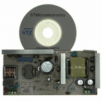
BOARD DEMO FOR L6563/LL6566A
Manufacturer
STMicroelectronics
Type
Power Factor Correctionr
Specifications of EVL6566A-75WES4
Main Purpose
AC/DC, Primary and Secondary Side with PFC
Outputs And Type
1, Isolated
Power - Output
75W
Voltage - Output
19V
Current - Output
4A
Voltage - Input
90 ~ 264VAC
Regulator Topology
Flyback
Board Type
Fully Populated
Utilized Ic / Part
L6563, L6566A, TSM1014
Input Voltage
90 V to 264 V
Output Voltage
19 V
Dimensions
78 mm x 170 mm
Product
Power Management Modules
Lead Free Status / RoHS Status
Lead free / RoHS Compliant
Frequency - Switching
-
Lead Free Status / Rohs Status
Lead free / RoHS Compliant
For Use With/related Products
L6563S, L6566A
Other names
497-8834
Available stocks
Company
Part Number
Manufacturer
Quantity
Price


Application information
5.5
26/51
PWM control block
The device is specific for secondary feedback. Typically, there is a TL431 on the secondary
side and an optocoupler that transfers output voltage information to the PWM control on the
primary side, crossing the isolation barrier. The PWM control input (pin 9, COMP) is driven
directly by the phototransistor's collector (the emitter is grounded to GND) to modulate the
duty cycle (
In applications where a tight output regulation is not required, it is possible to use a primary-
sensing feedback technique. In this approach the voltage generated by the self-supply
winding is sensed and regulated. This solution, shown in
is cheaper because no optocoupler or secondary reference is needed, but output voltage
regulation, especially as a result of load changes, is quite poor. Ideally, the voltage
generated by the self-supply winding and the output voltage should be related by the
Naux/Ns turn ratio only. Actually, numerous non-idealities, mainly transformer's parasites,
cause the actual ratio to deviate from the ideal one. Line regulation is quite good, in the
range of ± 2 %, whereas load regulation is about ±5 % and output voltage tolerance is in the
range of ±10 %.
The dynamics of the pin is in the 2.5 to 5 V range. The voltage at the pin is clamped
downwards at about 2 V. If the clamp is externally overridden and the voltage on the pin is
pulled below 1.4 V the L6566A will shut down. This condition is latched as long as the
device is supplied. While the device is disabled, however, no energy is coming from the self-
supply circuit, thus the voltage on the Vcc capacitor will decay and cross the UVLO
threshold after some time, which clears the latch and lets the HV generator restart. This
function is intended for an externally controlled burst-mode operation at light load with a
reduced output voltage, a technique typically used in multi-output SMPS, such as those for
CRT TVs or monitors (see the timing diagram
Figure 14. Possible feedback configurations that can be used with the L6566A
L6566A
Secondary feedback
Figure 14
9
COMP
TL431
, left-hand side circuit).
Vout
Figure 15 on page 27
COMP
L6566A
9
Figure 14
Primary feedback
5
Vcc
, right-hand side circuit,
).
Cs
L6566A
N
aux
Related parts for EVL6566A-75WES4
Image
Part Number
Description
Manufacturer
Datasheet
Request
R

Part Number:
Description:
BOARD EVAL FOR L6566A
Manufacturer:
STMicroelectronics
Datasheet:

Part Number:
Description:
STMicroelectronics [RIPPLE-CARRY BINARY COUNTER/DIVIDERS]
Manufacturer:
STMicroelectronics
Datasheet:
Part Number:
Description:
STMicroelectronics [LIQUID-CRYSTAL DISPLAY DRIVERS]
Manufacturer:
STMicroelectronics
Datasheet:

Part Number:
Description:
BOARD EVAL FOR MEMS SENSORS
Manufacturer:
STMicroelectronics
Datasheet:
Part Number:
Description:
NPN TRANSISTOR POWER MODULE
Manufacturer:
STMicroelectronics
Datasheet:
Part Number:
Description:
TURBOSWITCH ULTRA-FAST HIGH VOLTAGE DIODE
Manufacturer:
STMicroelectronics
Datasheet:
Part Number:
Description:
Manufacturer:
STMicroelectronics
Datasheet:
Part Number:
Description:
DIODE / SCR MODULE
Manufacturer:
STMicroelectronics
Datasheet:
Part Number:
Description:
DIODE / SCR MODULE
Manufacturer:
STMicroelectronics
Datasheet:
Part Number:
Description:
Search -----> STE16N100
Manufacturer:
STMicroelectronics
Datasheet:
Part Number:
Description:
Search ---> STE53NA50
Manufacturer:
STMicroelectronics
Datasheet:
Part Number:
Description:
NPN Transistor Power Module
Manufacturer:
STMicroelectronics
Datasheet: