EVL6566A-75WES4 STMicroelectronics, EVL6566A-75WES4 Datasheet - Page 5
EVL6566A-75WES4
Manufacturer Part Number
EVL6566A-75WES4
Description
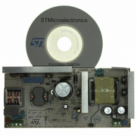
BOARD DEMO FOR L6563/LL6566A
Manufacturer
STMicroelectronics
Type
Power Factor Correctionr
Specifications of EVL6566A-75WES4
Main Purpose
AC/DC, Primary and Secondary Side with PFC
Outputs And Type
1, Isolated
Power - Output
75W
Voltage - Output
19V
Current - Output
4A
Voltage - Input
90 ~ 264VAC
Regulator Topology
Flyback
Board Type
Fully Populated
Utilized Ic / Part
L6563, L6566A, TSM1014
Input Voltage
90 V to 264 V
Output Voltage
19 V
Dimensions
78 mm x 170 mm
Product
Power Management Modules
Lead Free Status / RoHS Status
Lead free / RoHS Compliant
Frequency - Switching
-
Lead Free Status / Rohs Status
Lead free / RoHS Compliant
For Use With/related Products
L6563S, L6566A
Other names
497-8834
Available stocks
Company
Part Number
Manufacturer
Quantity
Price


L6566A
List of figures
Figure 1.
Figure 2.
Figure 3.
Figure 4.
Figure 5.
Figure 6.
Figure 7.
Figure 8.
Figure 9.
Figure 10.
Figure 11.
Figure 12.
Figure 13.
Figure 14.
Figure 15.
Figure 16.
Figure 17.
Figure 18.
Figure 19.
Figure 20.
Figure 21.
Figure 22.
Figure 23.
Figure 24.
Figure 25.
Figure 26.
Figure 27.
Figure 28.
Figure 29.
Figure 30.
Figure 31.
Figure 32.
Block diagram . . . . . . . . . . . . . . . . . . . . . . . . . . . . . . . . . . . . . . . . . . . . . . . . . . . . . . . . . . . . 1
Typical system block diagram. . . . . . . . . . . . . . . . . . . . . . . . . . . . . . . . . . . . . . . . . . . . . . . . 7
Pin connection (through top view) . . . . . . . . . . . . . . . . . . . . . . . . . . . . . . . . . . . . . . . . . . . . 8
Multi-mode operation with QR option active . . . . . . . . . . . . . . . . . . . . . . . . . . . . . . . . . . . . 17
High-voltage start-up generator: internal schematic . . . . . . . . . . . . . . . . . . . . . . . . . . . . . . 18
Timing diagram: normal power-up and power-down sequences . . . . . . . . . . . . . . . . . . . . 19
Timing diagram showing short-circuit behavior (SS pin clamped at 5 V) . . . . . . . . . . . . . . 20
Zero current detection block, triggering block, oscillator block and related logic . . . . . . . . 20
Drain ringing cycle skipping as the load is gradually reduced . . . . . . . . . . . . . . . . . . . . . . 21
Operation of ZCD, triggering and oscillator blocks (QR option active) . . . . . . . . . . . . . . . . 23
Load-dependent operating modes: timing diagrams . . . . . . . . . . . . . . . . . . . . . . . . . . . . . 24
Addition of an offset to the current sense lowers the burst-mode operation threshold . . . . 25
Possible feedback configurations that can be used with the L6566A . . . . . . . . . . . . . . . . . 26
Externally controlled burst-mode operation by driving pin COMP: timing diagram. . . . . . . 27
Typical power capability change vs input voltage in QR flyback converters . . . . . . . . . . . 28
Left: overcurrent setpoint vs VFF voltage; right: line feedforward function block . . . . . . . . 29
Hiccup-mode OCP: timing diagram . . . . . . . . . . . . . . . . . . . . . . . . . . . . . . . . . . . . . . . . . . 31
Possible interfaces between the L6566A and a PFC controller . . . . . . . . . . . . . . . . . . . . . 32
Operation after latched disable activation: timing diagram . . . . . . . . . . . . . . . . . . . . . . . . . 33
Soft-start pin operation under different operating conditions and settings . . . . . . . . . . . . . 34
OVP Function: internal block diagram . . . . . . . . . . . . . . . . . . . . . . . . . . . . . . . . . . . . . . . . 35
OVP function: timing diagram . . . . . . . . . . . . . . . . . . . . . . . . . . . . . . . . . . . . . . . . . . . . . . . 36
Maximum allowed duty cycle vs switching frequency for correct OVP detection . . . . . . . . 37
Brownout protection: internal block diagram and timing diagram . . . . . . . . . . . . . . . . . . . . 38
AC voltage sensing with the L6566A . . . . . . . . . . . . . . . . . . . . . . . . . . . . . . . . . . . . . . . . . 39
Slope compensation waveforms . . . . . . . . . . . . . . . . . . . . . . . . . . . . . . . . . . . . . . . . . . . . . 40
Typical low-cost application schematic . . . . . . . . . . . . . . . . . . . . . . . . . . . . . . . . . . . . . . . . 44
Typical full-feature application schematic (QR operation) . . . . . . . . . . . . . . . . . . . . . . . . . 44
Typical full-feature application schematic (FF operation) . . . . . . . . . . . . . . . . . . . . . . . . . . 45
Frequency foldback at light load (FF operation) . . . . . . . . . . . . . . . . . . . . . . . . . . . . . . . . 46
Latched shutdown upon mains overvoltage . . . . . . . . . . . . . . . . . . . . . . . . . . . . . . . . . . . . 46
Adaptive UVLO block. . . . . . . . . . . . . . . . . . . . . . . . . . . . . . . . . . . . . . . . . . . . . . . . . . . . . 25
List of figures
5/51
Related parts for EVL6566A-75WES4
Image
Part Number
Description
Manufacturer
Datasheet
Request
R

Part Number:
Description:
BOARD EVAL FOR L6566A
Manufacturer:
STMicroelectronics
Datasheet:

Part Number:
Description:
STMicroelectronics [RIPPLE-CARRY BINARY COUNTER/DIVIDERS]
Manufacturer:
STMicroelectronics
Datasheet:
Part Number:
Description:
STMicroelectronics [LIQUID-CRYSTAL DISPLAY DRIVERS]
Manufacturer:
STMicroelectronics
Datasheet:

Part Number:
Description:
BOARD EVAL FOR MEMS SENSORS
Manufacturer:
STMicroelectronics
Datasheet:
Part Number:
Description:
NPN TRANSISTOR POWER MODULE
Manufacturer:
STMicroelectronics
Datasheet:
Part Number:
Description:
TURBOSWITCH ULTRA-FAST HIGH VOLTAGE DIODE
Manufacturer:
STMicroelectronics
Datasheet:
Part Number:
Description:
Manufacturer:
STMicroelectronics
Datasheet:
Part Number:
Description:
DIODE / SCR MODULE
Manufacturer:
STMicroelectronics
Datasheet:
Part Number:
Description:
DIODE / SCR MODULE
Manufacturer:
STMicroelectronics
Datasheet:
Part Number:
Description:
Search -----> STE16N100
Manufacturer:
STMicroelectronics
Datasheet:
Part Number:
Description:
Search ---> STE53NA50
Manufacturer:
STMicroelectronics
Datasheet:
Part Number:
Description:
NPN Transistor Power Module
Manufacturer:
STMicroelectronics
Datasheet: