AD9117-EBZ Analog Devices Inc, AD9117-EBZ Datasheet - Page 43
AD9117-EBZ
Manufacturer Part Number
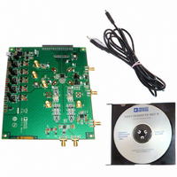
AD9117-EBZ
Description
BOARD EVALUATION FOR AD9117
Manufacturer
Analog Devices Inc
Series
TxDAC®r
Datasheet
1.AD9114BCPZ.pdf
(80 pages)
Specifications of AD9117-EBZ
Number Of Dac's
2
Number Of Bits
14
Outputs And Type
2, Differential
Sampling Rate (per Second)
125M
Data Interface
Serial
Dac Type
Current
Voltage Supply Source
Analog and Digital
Operating Temperature
-40°C ~ 85°C
Utilized Ic / Part
AD9117
Lead Free Status / RoHS Status
Lead free / RoHS Compliant


REFERENCE OPERATION
The AD9114/AD9115/AD9116/AD9117 contains an internal
1.0 V band gap reference. The internal reference can be disabled by
setting Bit 0 (EXTREF) of the power-down register (Address 0x01)
through the SPI interface. To use the internal reference, decouple
the REFIO pin to AVSS with a 0.1 μF capacitor, enable the
internal reference, and clear Bit 0 of the power-down register
(Address 0x01) through the SPI interface. Note that this is the
default configuration. The internal reference voltage is present
at REFIO. If the voltage at REFIO is to be used anywhere else in
the circuit, an external buffer amplifier with an input bias current of
less than 100 nA must be used to avoid loading the reference. An
example of the use of the internal reference is shown in Figure 96.
REFIO serves as either an input or an output, depending on
whether the internal or an external reference is used. Table 17
summarizes the reference operation.
Table 17. Reference Operation
Reference Mode
Internal
External
An external reference can be used in applications requiring tighter
gain tolerances or lower temperature drift. In addition, a variable
external voltage reference can be used to implement a method
for gain control of the DAC output.
Recommendations When Using an External Reference
Apply the external reference to the REFIO pin. The internal
reference can be directly overdriven by the external reference,
or the internal reference can be powered down to save power
consumption.
The external 0.1 μF compensation capacitor on REFIO is not
required unless specified by the external voltage reference
manufacturer. The input impedance of REFIO is 10 kΩ when
the internal reference is powered up and 1 MΩ when it is
powered down.
0.1µF
AVSS
xR
FSADJx
SET
REFIO
Figure 96. Internal Reference Configuration
I
xREF
1.0V
V
REFIO Pin
Connect 0.1 μF
capacitor
Apply external
capacitor
BG
–
+
AD9114/AD9115/
AD9116/AD9117
CURRENT
SCALING
x32
Register Setting
Register 0x01, Bit 0 = 0
(default)
Register 0x01, Bit 0 = 1
(for power saving)
I
xOUTFS
Q DAC
I DAC
OR
Rev. A | Page 43 of 80
REFERENCE CONTROL AMPLIFIER
The AD9114/AD9115/AD9116/AD9117 contains a control
amplifier that regulates the full-scale output current, I
The control amplifier is configured as a V-I converter, as shown
in Figure 96. The output current, I
the V
the DAC Transfer Function section). I
segmented current sources with the proper scale factor to set
I
section).
The control amplifier allows a 2.5:1 adjustment span of I
from 8 mA to 20 mA by setting I
(xR
I
power dissipation of the AD9114/AD9115/AD9116/AD9117,
which is proportional to I
section). The second benefit relates to the ability to adjust the
output over a 8 dB range with 0.25 dB steps, which is useful for
controlling the transmitted power. The small signal bandwidth
of the reference control amplifier is approximately 500 kHz.
This allows the device to be used for low frequency, small
signal multiplying applications.
DAC TRANSFER FUNCTION
The AD9114/AD9115/AD9116/AD9117 provides two differential
current outputs, IOUTP/IOUTN and QOUTP/ QOUTN. IOUTP
and QOUTP provide a near full-scale current output, I
when all bits are high (that is, DAC CODE = 2
10, 12, or 14 for the AD9114, AD9115, AD9116, and AD9117,
respectively), while IOUTN and QOUTN, the complementary
outputs, provide no current. The current outputs appearing at the
positive DAC outputs, IOUTP and QOUTP, and at the negative
DAC outputs, IOUTN and QOUTN, are a function of both the
input code and I
where:
IDAC CODE and QDAC CODE = 0 to 2
representation).
I
and I
voltage, V
I
xOUTFS
xOUTFS
IOUTFS
IOUTFS
SET
IOUTP = (IDAC CODE/2
QOUTP = (QDAC CODE/2
IOUTN = ((2
QOUTN = ((2
I
I
where:
I
I
QREF
REFIO
IOUTFS
QOUTFS
IREF
QREF
, as stated in Equation 3 (see the DAC Transfer Function
and I
and I
between 1.6 kΩ and 4 kΩ). The wide adjustment span of
provides several benefits. The first relates directly to the
, respectively, which are nominally set by a reference
= V
REFIO
and an external resistor, xR
= V
= 32 × I
QOUTFS
AD9114/AD9115/AD9116/AD9117
QOUTFS
= 32 × I
REFIO
, and external resistors, IR
REFIO
xOUTFS
/IR
/QR
can be expressed as follows:
are functions of the reference currents, I
N
N
IREF
− 1) − IDAC CODE)/2
QREF
SET
− 1) − QDAC CODE)/2
SET
and can be expressed as follows:
xOUTFS
N
xREF
(see the DAC Transfer Function
) × I
N
xREF
) × I
between 250 μA and 625 μA
SET
, is determined by the ratio of
IOUTFS
xREF
, as stated in Equation 4 (see
QOUTFS
SET
N
and QR
is mirrored to the
− 1 (that is, decimal
N
× I
N
N
− 1, where N = 8,
× I
IOUTFS
SET,
QOUTFS
respectively.
xOUTFS
xOUTFS
xOUTFS
IREF
.
,
(1)
(2)
(3)
(4)
Related parts for AD9117-EBZ
Image
Part Number
Description
Manufacturer
Datasheet
Request
R

Part Number:
Description:
Dual 14B, Low Power D-A Converter
Manufacturer:
Analog Devices Inc
Datasheet:

Part Number:
Description:
±1.7g Dual-Axis IMEMS Accelerometer Evaluation Board
Manufacturer:
Analog Devices Inc
Datasheet:
Part Number:
Description:
Inertial Sensor Evaluation System
Manufacturer:
Analog Devices Inc
Datasheet:
Part Number:
Description:
Manufacturer:
Analog Devices Inc
Datasheet:
Part Number:
Description:
Manufacturer:
Analog Devices Inc
Datasheet:
Part Number:
Description:
Manufacturer:
Analog Devices Inc
Datasheet:
Part Number:
Description:
Manufacturer:
Analog Devices Inc
Datasheet:
Part Number:
Description:
Manufacturer:
Analog Devices Inc
Datasheet:
Part Number:
Description:
Manufacturer:
Analog Devices Inc
Datasheet:
Part Number:
Description:
Manufacturer:
Analog Devices Inc
Datasheet:
Part Number:
Description:
Manufacturer:
Analog Devices Inc
Datasheet:
Part Number:
Description:
Manufacturer:
Analog Devices Inc
Datasheet:
Part Number:
Description:
Manufacturer:
Analog Devices Inc
Datasheet: