AD9785-EBZ Analog Devices Inc, AD9785-EBZ Datasheet - Page 30
AD9785-EBZ
Manufacturer Part Number
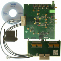
AD9785-EBZ
Description
BOARD EVAL FOR AD9785
Manufacturer
Analog Devices Inc
Series
TxDAC®r
Datasheet
1.AD9785BSVZ.pdf
(64 pages)
Specifications of AD9785-EBZ
Number Of Dac's
2
Number Of Bits
12
Outputs And Type
2, Differential
Sampling Rate (per Second)
800M
Data Interface
Serial
Settling Time
22ms
Dac Type
Current
Voltage Supply Source
Analog and Digital
Operating Temperature
-40°C ~ 85°C
Utilized Ic / Part
AD9785
Silicon Manufacturer
Analog Devices
Application Sub Type
DAC
Kit Application Type
Data Converter
Silicon Core Number
AD9785
Kit Contents
Board
Lead Free Status / RoHS Status
Lead free / RoHS Compliant
Lead Free Status / RoHS Status
Lead free / RoHS Compliant, Lead free / RoHS Compliant


AD9785/AD9787/AD9788
The Auxiliary DAC 1 control register comprises two bytes located at Address 0x06. These bits are routed directly to the periphery of the
digital logic. No digital functionality within the main digital block is required.
Table 16. Auxiliary DAC 1 Control Register
Address
0x06
The Q DAC control register comprises two bytes located at Address 0x07. These bits are routed directly to the periphery of the digital
logic. No digital functionality within the main digital block is required.
Table 17. Q DAC Control Register
Address
0x07
The Auxiliary DAC 2 control register comprises two bytes located at Address 0x08. These bits are routed directly to the periphery of the
digital logic. No digital functionality within the main digital block is required.
Table 18. Auxiliary DAC 2 Control Register
Address
0x08
Bit
[15]
[14]
[13]
[12:10]
[9:0]
Bit
[15]
[14]
[13:10]
[9:0]
Bit
[15]
[14]
[13]
[12:10]
[9:0]
Name
Auxiliary DAC 1 sign
Auxiliary DAC 1
current direction
Auxiliary DAC 1
power-down
Reserved
Auxiliary DAC 1 data
Name
Q DAC sleep
Q DAC power-down
Reserved
Q DAC gain adjustment
Auxiliary DAC 2 sign
Auxiliary DAC 2
current direction
Auxiliary DAC 2
power-down
Reserved
Auxiliary DAC 2 data
Name
0: Default. If the Auxiliary DAC 1 sign bit is cleared, the Aux DAC 1 sign is positive.
Pin 90 is the active pin.
1: If the Auxiliary DAC 1 sign bit is set, the Aux DAC 1 sign is negative. Pin 89 is the
active pin.
0: Default. If the Auxiliary DAC 1 current direction bit is cleared, the Aux DAC 1 sources
current.
1: If the Auxiliary DAC 1 current direction bit is set, the Aux DAC 1 sinks current.
0: Default. If the Auxiliary DAC 1 power-down bit is cleared, the Aux DAC 1 is active.
1: If the Auxiliary DAC 1 power-down bit is set, the Aux DAC 1 is inactive and enters a
low power state.
Reserved for future use.
These bits are the Auxiliary DAC 1 gain adjustment bits.
Description
Description
0: Default. If the Q DAC sleep bit is cleared, the Q DAC is active.
1: If the Q DAC sleep bit is set, the Q DAC is inactive and enters a low power state.
0: Default. If the Q DAC power-down bit is cleared, the Q DAC is active.
1: If the Q DAC power-down bit is set, the Q DAC is inactive and enters a low power state.
Reserved for future use.
These bits are the Q DAC gain adjustment bits.
Description
0: Default. If the Auxiliary DAC 2 sign bit is cleared, the Aux DAC 2 sign is positive.
Pin 86 is the active pin.
1: If the Auxiliary DAC 2 sign bit is set, the Aux DAC 2 sign is negative. Pin 87 is the
active pin.
0: Default. If the Auxiliary DAC 2 current direction bit is cleared, the Aux DAC 2 sources
current.
1: If the Auxiliary DAC 2 current direction bit is set, the Aux DAC 2 sinks current.
0: Default. If the Auxiliary DAC 2 power-down bit is cleared, the Aux DAC 2 is active.
1: If the Auxiliary DAC 2 power-down bit is set, the Aux DAC 2 is inactive and enters
a low power state.
Reserved for future use.
These bits are the Auxiliary DAC 2 gain adjustment bits.
Rev. A | Page 30 of 64
Related parts for AD9785-EBZ
Image
Part Number
Description
Manufacturer
Datasheet
Request
R

Part Number:
Description:
Dual 16B, 1.0 GSPS TxDAC
Manufacturer:
Analog Devices Inc
Datasheet:

Part Number:
Description:
±1.7g Dual-Axis IMEMS Accelerometer Evaluation Board
Manufacturer:
Analog Devices Inc
Datasheet:
Part Number:
Description:
Inertial Sensor Evaluation System
Manufacturer:
Analog Devices Inc
Datasheet:
Part Number:
Description:
Manufacturer:
Analog Devices Inc
Datasheet:
Part Number:
Description:
Manufacturer:
Analog Devices Inc
Datasheet:
Part Number:
Description:
Manufacturer:
Analog Devices Inc
Datasheet:
Part Number:
Description:
Manufacturer:
Analog Devices Inc
Datasheet:
Part Number:
Description:
Manufacturer:
Analog Devices Inc
Datasheet:
Part Number:
Description:
Manufacturer:
Analog Devices Inc
Datasheet:
Part Number:
Description:
Manufacturer:
Analog Devices Inc
Datasheet:
Part Number:
Description:
Manufacturer:
Analog Devices Inc
Datasheet:
Part Number:
Description:
Manufacturer:
Analog Devices Inc
Datasheet:
Part Number:
Description:
Manufacturer:
Analog Devices Inc
Datasheet: