AD9785-EBZ Analog Devices Inc, AD9785-EBZ Datasheet - Page 31
AD9785-EBZ
Manufacturer Part Number
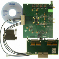
AD9785-EBZ
Description
BOARD EVAL FOR AD9785
Manufacturer
Analog Devices Inc
Series
TxDAC®r
Datasheet
1.AD9785BSVZ.pdf
(64 pages)
Specifications of AD9785-EBZ
Number Of Dac's
2
Number Of Bits
12
Outputs And Type
2, Differential
Sampling Rate (per Second)
800M
Data Interface
Serial
Settling Time
22ms
Dac Type
Current
Voltage Supply Source
Analog and Digital
Operating Temperature
-40°C ~ 85°C
Utilized Ic / Part
AD9785
Silicon Manufacturer
Analog Devices
Application Sub Type
DAC
Kit Application Type
Data Converter
Silicon Core Number
AD9785
Kit Contents
Board
Lead Free Status / RoHS Status
Lead free / RoHS Compliant
Lead Free Status / RoHS Status
Lead free / RoHS Compliant, Lead free / RoHS Compliant


The interrupt control register comprises two bytes located at Address 0x09. Bits [11:10] and Bits [7:3] are read-only bits that indicate the
current status of a specific event that may cause an interrupt request (IRQ pin active low). These bits are controlled via the digital logic
and are read only via the serial port. Bits [1:0] are the IRQ mask (or enable) bits, which are writable by the user and can also be read back.
Table 19. Interrupt Control Register
Address
0x09
Bit
[15:13]
[12]
[11]
[10]
[9:8]
[7]
[6]
[5]
[4]
[3]
[2]
[1]
[0]
Name
Reserved
Clear lock indicator
Sync lock lost status
Sync lock status
Reserved
Data timing error IRQ
Sync timing error IRQ
Data timing error type
Sync timing error type
PLL lock indicator
Reserved
Data port IRQ enable
Sync port IRQ enable
Reserved for future use.
Writing a 1 to this bit clears the sync lock lost status bit. This bit does not automatically
reset itself to 0 when the reset is complete.
When high, this bit indicates that the device has lost synchronization. This bit is latched
and does not reset automatically after the device regains synchronization. To reset this
bit to 0, a 1 must be written to the clear lock indicator bit.
When this bit is low, the device is not synchronized. When this bit is high, the device is
synchronized.
Reserved for future use.
0: Default. No setup or hold time error has been detected via the input data port
setup/hold error checking logic.
1: A setup or hold time error has been detected via the input data port setup/hold error
checking logic.
0: Default. No setup or hold time error has been detected via the multichip
synchronization receive pulse setup/hold error checking logic.
1: A setup or hold time error has been detected via the multichip synchronization
receive pulse setup/hold error checking logic.
0: Default. A hold error has been detected via the input data port setup/hold error
checking logic. This bit is valid only if the data timing error IRQ bit (Bit 7) is set.
1: A setup error has been detected via the input data port setup/hold error checking
logic. This bit is valid only if the data timing error IRQ bit (Bit 7) bit is set.
0: Default. A hold error has been detected via the multichip synchronization receive
pulse setup/hold error checking logic. This bit is valid only if the sync timing error IRQ
bit (Bit 6) is set.
1: A setup error has been detected via the multichip synchronization receive pulse
setup/hold error checking logic. This bit is valid only if the sync timing error IRQ bit
(Bit 6) is set.
0: Default. The PLL clock multiplier is not locked to the input reference clock.
1: The PLL clock multiplier is locked to the input reference clock.
Reserved for future use.
0: Default. The data IRQ bit (and the IRQ pin) are not enabled (masked) for any errors
that may be detected via the input data port setup/hold error checking logic.
1: The data IRQ bit (and the IRQ pin) are enabled and go active if a setup or hold error is
detected via the input data port setup/hold error checking logic.
0: Default. The sync IRQ bit (and the IRQ pin) are not enabled (masked) for any errors
that may be detected via the multichip synchronization receive pulse setup/hold error
checking logic.
1: The sync IRQ bit (and the IRQ pin) are enabled and go active if a setup or hold error
is detected via the multichip synchronization receive pulse setup/hold error checking
logic.
Description
Rev. A | Page 31 of 64
AD9785/AD9787/AD9788
Related parts for AD9785-EBZ
Image
Part Number
Description
Manufacturer
Datasheet
Request
R

Part Number:
Description:
Dual 16B, 1.0 GSPS TxDAC
Manufacturer:
Analog Devices Inc
Datasheet:

Part Number:
Description:
±1.7g Dual-Axis IMEMS Accelerometer Evaluation Board
Manufacturer:
Analog Devices Inc
Datasheet:
Part Number:
Description:
Inertial Sensor Evaluation System
Manufacturer:
Analog Devices Inc
Datasheet:
Part Number:
Description:
Manufacturer:
Analog Devices Inc
Datasheet:
Part Number:
Description:
Manufacturer:
Analog Devices Inc
Datasheet:
Part Number:
Description:
Manufacturer:
Analog Devices Inc
Datasheet:
Part Number:
Description:
Manufacturer:
Analog Devices Inc
Datasheet:
Part Number:
Description:
Manufacturer:
Analog Devices Inc
Datasheet:
Part Number:
Description:
Manufacturer:
Analog Devices Inc
Datasheet:
Part Number:
Description:
Manufacturer:
Analog Devices Inc
Datasheet:
Part Number:
Description:
Manufacturer:
Analog Devices Inc
Datasheet:
Part Number:
Description:
Manufacturer:
Analog Devices Inc
Datasheet:
Part Number:
Description:
Manufacturer:
Analog Devices Inc
Datasheet: