CDB4398 Cirrus Logic Inc, CDB4398 Datasheet - Page 23
CDB4398
Manufacturer Part Number
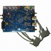
CDB4398
Description
BOARD EVAL FOR CS4398 DAC
Manufacturer
Cirrus Logic Inc
Specifications of CDB4398
Number Of Dac's
2
Number Of Bits
24
Outputs And Type
2, Differential
Sampling Rate (per Second)
192k
Data Interface
I²C, SPI™
Dac Type
Voltage
Voltage Supply Source
Analog and Digital
Operating Temperature
-10°C ~ 70°C
Utilized Ic / Part
CS4398
Description/function
Audio D/A
Operating Supply Voltage
5 V
Product
Audio Modules
For Use With/related Products
CS4398
Lead Free Status / RoHS Status
Contains lead / RoHS non-compliant
Lead Free Status / RoHS Status
Lead free / RoHS Compliant, Contains lead / RoHS non-compliant
Other names
598-1155


DS568F1
4.6.1
4.7
4.7.1
4.7.2
4.7.3
4.7.4
4.7.5
Control Port Mode
2. Bring RST high. Set the CPEN bit (Reg. 8h) prior to the completion of the Stand-Alone power-up se-
3. Clear the PDN bit to initiate the power-up sequence.
If the CPEN bit is not written within the allotted time, the device will start-up in stand-alone mode and begin
converting data according to the current state of the M0 to M3 pins. Since these pins are also the control
port pins an undesired mode may be entered. For this reason, if the CPEN bit is not set before the allotted
time elapses, the SDIN line must be kept at static 0 (not dithered) until the device is properly configured.
This will keep the device from converting data improperly.
Recommended Power-up Sequence (Stand-Alone Mode)
1. Hold RST low until the power supply, master, and left/right clocks are stable. In this state, the Control
2. Bring RST high. The device will remain in a low power state and will initiate the Stand-Alone power-
Recommended Power-up Sequence (Control Port Mode)
1. Hold RST low until the power supply, master, and left/right clocks are stable. In this state, the Control
Sample Rate Range/Oversampling Mode (Control Port Mode)
Sample rate mode selection is determined by the FM bits (Reg. 02h).
Serial Audio Interface Formats (Control Port Mode)
The desired serial audio interface format is selected using the DIF2:0 bits (Reg. 02h).
MUTEC Pins (Control Port Mode)
The auto-mute polarity feature (mentioned in Section 4.3) is defeatable. The MUTEP1:0 bits in register
04h give the option to override the mute polarity which was auto detected at startup (see the Register De-
scription section for more details).
Interpolation Filter (Control Port Mode)
To accommodate the increasingly complex requirements of digital audio systems, the CS4398 incorpo-
rates selectable interpolation filters. A fast and a slow roll-off filter are available in each of Single-, Double-
, and Quad-Speed modes. These filters have been designed to accommodate a variety of musical tastes
and styles. The FILT_SEL bit (Reg. 07h) is used to select which filter is used (see the Register Description
section for more details).
Filter specifications can be found in Section 2, and filter response plots can be found in Figures 20 to 43
in the “Appendix” on page 41.
quence (approximately 2
and initializes the Control Port to its default settings. The desired register settings can be loaded while
keeping the PDN bit (Reg. 8h) set to 1.
Port is reset to its default settings.
up sequence following approximately 2
Port is reset to its default settings.
18
MCLK cycles). Setting this bit halts the Stand-Alone power-up sequence
18
MCLK cycles.
CS4398
23
Related parts for CDB4398
Image
Part Number
Description
Manufacturer
Datasheet
Request
R

Part Number:
Description:
Development Kit
Manufacturer:
Cirrus Logic Inc
Datasheet:
Part Number:
Description:
Development Kit
Manufacturer:
Cirrus Logic Inc
Datasheet:


Part Number:
Description:
High-efficiency PFC + Fluorescent Lamp Driver Reference Design
Manufacturer:
Cirrus Logic Inc
Datasheet:
Part Number:
Description:
Development Kit
Manufacturer:
Cirrus Logic Inc
Datasheet:
Part Number:
Description:
Development Kit
Manufacturer:
Cirrus Logic Inc
Datasheet:

Part Number:
Description:
Development Kit
Manufacturer:
Cirrus Logic Inc
Datasheet:
Part Number:
Description:
Development Kit
Manufacturer:
Cirrus Logic Inc
Datasheet:
Part Number:
Description:
Development Kit
Manufacturer:
Cirrus Logic Inc
Datasheet:
Part Number:
Description:
Development Kit
Manufacturer:
Cirrus Logic Inc
Datasheet:

Part Number:
Description:
EVALUATION BOARD FOR CS8427
Manufacturer:
Cirrus Logic Inc
Datasheet:

Part Number:
Description:
BOARD EVAL FOR CS8416 RCVR
Manufacturer:
Cirrus Logic Inc
Datasheet:

Part Number:
Description:
EVALUATION BOARD FOR CS8420
Manufacturer:
Cirrus Logic Inc
Datasheet:

Part Number:
Description:
KIT DEVELOPMENT EP9315 ARM9
Manufacturer:
Cirrus Logic Inc
Datasheet:

Part Number:
Description:
KIT DEVELOPMENT EP9302 ARM9
Manufacturer:
Cirrus Logic Inc
Datasheet: