CDB4398 Cirrus Logic Inc, CDB4398 Datasheet - Page 26
CDB4398
Manufacturer Part Number
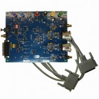
CDB4398
Description
BOARD EVAL FOR CS4398 DAC
Manufacturer
Cirrus Logic Inc
Specifications of CDB4398
Number Of Dac's
2
Number Of Bits
24
Outputs And Type
2, Differential
Sampling Rate (per Second)
192k
Data Interface
I²C, SPI™
Dac Type
Voltage
Voltage Supply Source
Analog and Digital
Operating Temperature
-10°C ~ 70°C
Utilized Ic / Part
CS4398
Description/function
Audio D/A
Operating Supply Voltage
5 V
Product
Audio Modules
For Use With/related Products
CS4398
Lead Free Status / RoHS Status
Contains lead / RoHS non-compliant
Lead Free Status / RoHS Status
Lead free / RoHS Compliant, Contains lead / RoHS non-compliant
Other names
598-1155


26
5.4.1
5.4.2
5.5
5.5.1
SPI Format
In SPI format, CS is the CS4398 chip select signal; CCLK is the Control Port bit clock; CDIN is the input
data line from the microcontroller; CDOUT is the output data line and the chip address is 1001100. CS,
CCLK,and CDIN are all inputs, and data is clocked in on the rising edge of CCLK. CDOUT is an output and
is high-impedance when not actively outputting data.
Writing in I²C Format
To communicate with the CS4398, initiate a START condition of the bus (see Figure 14.). Next, send the
chip address. The eighth bit of the address byte is the R/W bit (low for a write). The next byte is the Mem-
ory Address Pointer, MAP, which selects the register to be read or written. The MAP is then followed by
the data to be written. To write multiple registers, continue providing a clock and data, waiting for the
CS4398 to acknowledge between each byte. To end the transaction, send a STOP condition.
Reading in I²C Format
To communicate with the CS4398, initiate a START condition of the bus (see Figure 14.). Next, send the
chip address. The eighth bit of the address byte is the R/W bit (high for a read). The contents of the reg-
ister pointed to by the MAP will be output after the chip address. To read multiple registers, continue pro-
viding a clock and issue an ACK after each byte. To end the transaction, send a STOP condition.
Writing in SPI
Figure 15 shows the operation of the Control Port in SPI format. To write to a register, bring CS low. The
first seven bits on CDIN form the chip address and must be 1001100. The eighth bit is a read/write indi-
cator (R/W), which must be low to write. The next eight bits form the Memory Address Pointer (MAP),
which is set to the address of the register that is to be updated. The next eight bits are the data that will
be placed into register designated by the MAP. To write multiple registers, keep CS low and continue pro-
viding clocks on CCLK. End the read transaction by setting CS high.
S D A
S C L
N o te : If o p e ra tio n is a w rite , th is b y te c o n ta in s th e M e m o ry A d d re s s P o in te r, M A P .
S ta rt
1 0 0 1 1
A D 1
Figure 14. Control Port Timing, I²C Format
A D 0
R /W
A C K
D A T A
1-8
N o te 1
A C K
D A T A
1-8
A C K
CS4398
S to p
DS568F1
Related parts for CDB4398
Image
Part Number
Description
Manufacturer
Datasheet
Request
R

Part Number:
Description:
Development Kit
Manufacturer:
Cirrus Logic Inc
Datasheet:
Part Number:
Description:
Development Kit
Manufacturer:
Cirrus Logic Inc
Datasheet:


Part Number:
Description:
High-efficiency PFC + Fluorescent Lamp Driver Reference Design
Manufacturer:
Cirrus Logic Inc
Datasheet:
Part Number:
Description:
Development Kit
Manufacturer:
Cirrus Logic Inc
Datasheet:
Part Number:
Description:
Development Kit
Manufacturer:
Cirrus Logic Inc
Datasheet:

Part Number:
Description:
Development Kit
Manufacturer:
Cirrus Logic Inc
Datasheet:
Part Number:
Description:
Development Kit
Manufacturer:
Cirrus Logic Inc
Datasheet:
Part Number:
Description:
Development Kit
Manufacturer:
Cirrus Logic Inc
Datasheet:
Part Number:
Description:
Development Kit
Manufacturer:
Cirrus Logic Inc
Datasheet:

Part Number:
Description:
EVALUATION BOARD FOR CS8427
Manufacturer:
Cirrus Logic Inc
Datasheet:

Part Number:
Description:
BOARD EVAL FOR CS8416 RCVR
Manufacturer:
Cirrus Logic Inc
Datasheet:

Part Number:
Description:
EVALUATION BOARD FOR CS8420
Manufacturer:
Cirrus Logic Inc
Datasheet:

Part Number:
Description:
KIT DEVELOPMENT EP9315 ARM9
Manufacturer:
Cirrus Logic Inc
Datasheet:

Part Number:
Description:
KIT DEVELOPMENT EP9302 ARM9
Manufacturer:
Cirrus Logic Inc
Datasheet: