DK86060-3 Fujitsu Semiconductor America Inc, DK86060-3 Datasheet
DK86060-3
Specifications of DK86060-3


Related parts for DK86060-3


DK86060-3 Summary of contents
Page 1
Datasheet MB86060 16-bit Interpolating Digital to Analog Converter The Fujitsu MB86060 is a high performance 12-bit, 400MSa/s digital to analog converter (DAC) enhanced with a 16-bit interpolation filtering front-end. Use of novel techniques for the converter architecture delivers high speed ...
Page 2
MB86060 16-bit Interpolating Digital to Analog Converter Contents 1 Functional Description . . . . . . . . . . . . . . . . . . . . . . . . . . . . . ...
Page 3
February 2009 Version 2.0 FME/MS/SFDAC1/DS/4250 MB86060 16-bit Interpolating Digital to Analog Converter 5 Electrical Specifications . . . . . . . . . . . . . . . . . . . . . . . . . ...
Page 4
MB86060 16-bit Interpolating Digital to Analog Converter 1 Functional Description The MB86060 integrates a 12-bit 400MSa/s DAC core with selectable front end processing to provide input interpolation filtering, dither and noise shaping. Versatile interfacing via the 16-bit parallel CMOS data ...
Page 5
February 2009 Version 2.0 FME/MS/SFDAC1/DS/4250 MB86060 16-bit Interpolating Digital to Analog Converter 1.2 Clock The MB86060 incorporates a clock multiplier. This may be used to generate the internal x1, x2 and x4 clock signals required to clock the DAC core ...
Page 6
MB86060 16-bit Interpolating Digital to Analog Converter CLK In Data CLK XIN Figure 2 CLK In and Data CLK Timing 1.2.2 Clock Multiplier Modes The clock multiplier can be set in one of eight modes. These take the form of ...
Page 7
February 2009 Version 2.0 FME/MS/SFDAC1/DS/4250 MB86060 16-bit Interpolating Digital to Analog Converter Table 2: Multiplier and Filter Mode to DAC Update Frequency Cross Reference Matrix Filter Mode Bypass DAC IN DAC IN x1 ...
Page 8
MB86060 16-bit Interpolating Digital to Analog Converter The OSC[1:0] setting controls the delay response within the delay-lock-loop. Different settings are required to enable best jitter performance to be achieved and should be set according to the DAC clock rate being ...
Page 9
February 2009 Version 2.0 FME/MS/SFDAC1/DS/4250 MB86060 16-bit Interpolating Digital to Analog Converter 1.2.4 Clock Out A differential output clock (Data CLK) signal is available to act as a reference to clock data into the device. Data CLK is available on ...
Page 10
MB86060 16-bit Interpolating Digital to Analog Converter 1.4 Programmable Dither Dither can be added to improve low-level performance and reduce effects due to nonlinearities within the DAC, and reducing DNL and glitch energy. The dither has programmable amplitude, see Table ...
Page 11
February 2009 Version 2.0 FME/MS/SFDAC1/DS/4250 MB86060 16-bit Interpolating Digital to Analog Converter 1.6.1 Segment Shuffling The DAC core incorporates a proprietary segment shuffling capability which is provided to further improve linearity, and hence improve SFDR. This feature reduces any signal ...
Page 12
MB86060 16-bit Interpolating Digital to Analog Converter 1.8 Analog Output The DAC output is a differential current type. A termination resistor should be used appropriate for the maximum allowable output swing. A power down control places the analog circuitry in ...
Page 13
February 2009 Version 2.0 FME/MS/SFDAC1/DS/4250 MB86060 16-bit Interpolating Digital to Analog Converter 1.8.2 Analog Output Scaling Power savings can be made by reducing the full scale analog output current (I However, to maintain the specified performance, I should be pre-scaled ...
Page 14
MB86060 16-bit Interpolating Digital to Analog Converter 1.9.1 Data Timing Data should be clocked into the device with the rising edge of the Data CLK signal. The timing relationship between the rising edge of Data CLK and the setup and ...
Page 15
February 2009 Version 2.0 FME/MS/SFDAC1/DS/4250 MB86060 16-bit Interpolating Digital to Analog Converter 1.10.3 Pinout The MB86060 features a performance enhanced pinout to gain the maximum performance from the PCB. Ground connection pins are provided adjacent to clock in, clock out ...
Page 16
MB86060 16-bit Interpolating Digital to Analog Converter 2 Interpolating Filters The integration of interpolating filters provides a number of benefits to the system implementation. In general, improved performance can be gained by using a higher DAC conversion rate effectively providing ...
Page 17
February 2009 Version 2.0 FME/MS/SFDAC1/DS/4250 MB86060 16-bit Interpolating Digital to Analog Converter -4dB x1 mode 0 100 F DAT Filter Pass Band = 0.43.F DAT -0.9dB X2 (slow) mode 0 100 F DAT Filter Pass Band = 0.37.F DAT X2 ...
Page 18
MB86060 16-bit Interpolating Digital to Analog Converter x2 Slow Filter Pass Band 0.43fs (-0.1dB) Stop Band -75dBFS from 0.59fs [note: Frequency axis normalised to input data rate] x2 Fast Filter Pass Band 0.74fs (-0.1dB) Stop Band -83dBFS from 1.54fs [note: ...
Page 19
February 2009 Version 2.0 FME/MS/SFDAC1/DS/4250 MB86060 16-bit Interpolating Digital to Analog Converter CLK In D15 IOUT Data CLK A: x1 Interpolation Filter, Clock Multiplier Bypassed CLK In D15 IOUT Data CLK B: x2 slow Interpolation Filter, Clock Multiplier Bypassed CLK ...
Page 20
MB86060 16-bit Interpolating Digital to Analog Converter 3 Dither Frequency Spectrum The use of dither in data converter applications is not uncommon, where improvements in low-level performance and reduced effects due to nonlinearities can be achieved. For dither to be ...
Page 21
February 2009 Version 2.0 FME/MS/SFDAC1/DS/4250 MB86060 16-bit Interpolating Digital to Analog Converter 4 Application Notes 4.1 Power & Ground Plane Regions The following guidelines are suggested to obtain the specified performance. Any departure from these recommendations should be investigated to ...
Page 22
MB86060 16-bit Interpolating Digital to Analog Converter Another significant reason for splitting the digital data ground plane from the main digital ground is that when using a remote data generator (e.g. a benchtop pattern or data generator) there is a ...
Page 23
February 2009 Version 2.0 FME/MS/SFDAC1/DS/4250 MB86060 16-bit Interpolating Digital to Analog Converter DIGITAL REGION PSU Star point REFERENCE REGION Figure 12 Recommended Ground Plane Splits 4.2 Power Supplies Only one clean low-impedance power supply is required. Power distribution should be ...
Page 24
MB86060 16-bit Interpolating Digital to Analog Converter Power supply tracks should be kept as short and wide as possible. The ground and supply tracks should run adjacent to each other for as far as possible, whilst avoiding all signal tracks ...
Page 25
February 2009 Version 2.0 FME/MS/SFDAC1/DS/4250 MB86060 16-bit Interpolating Digital to Analog Converter 4.4 Input Data Interfacing The data input interface is a 16-bit wide CMOS bus, operating at speeds up to 200MHz. As such this bus can radiate large amounts ...
Page 26
MB86060 16-bit Interpolating Digital to Analog Converter 4.5 Analog Output To provide a differential analog output which is both isolated form the analog ground plane, and which gives good common mode rejection, a two stage transformer circuit can be used. ...
Page 27
February 2009 Version 2.0 FME/MS/SFDAC1/DS/4250 MB86060 16-bit Interpolating Digital to Analog Converter If a common, system wide logic level clock source used, this should be transformer coupled to remove common mode noise and isolate the clock ground ...
Page 28
MB86060 16-bit Interpolating Digital to Analog Converter 4.7 Clock Output The data clock output is provided as a reference to clock the data into the device. As with the analog output and the reference input it is recommended that the ...
Page 29
February 2009 Version 2.0 FME/MS/SFDAC1/DS/4250 MB86060 16-bit Interpolating Digital to Analog Converter 4.8 Signal Routing Where signals have to be tracked as differential pairs, attention should be paid to the routing and positioning of these tracks. Wherever possible, differential tracks ...
Page 30
MB86060 16-bit Interpolating Digital to Analog Converter 5 Electrical Specifications 5.1 Absolute Maximum Ratings Parameter Supply voltage Input Voltage Output Voltage Output Current Storage Temperature T (min (max), VDD = DVDD = RVDD = AVDD = CVDD = ...
Page 31
February 2009 Version 2.0 FME/MS/SFDAC1/DS/4250 MB86060 16-bit Interpolating Digital to Analog Converter 5.2 Digital Interface Specifications Parameter CMOS inputs High-level input voltage Low-level input voltage High-level input current Low-level input current Input capacitance Setup time Hold time CMOS outputs High-level ...
Page 32
MB86060 16-bit Interpolating Digital to Analog Converter 5.3 DC Specifications Parameter DC Accuracy Integral Non Linearity, (Shuffle Off) Differential Non Linearity Analog output Full scale output current Output resistance Output capacitance Gain error Output voltage (compliance) - Maximum Output voltage ...
Page 33
February 2009 Version 2.0 FME/MS/SFDAC1/DS/4250 MB86060 16-bit Interpolating Digital to Analog Converter T (min (max), VDD = DVDD = RVDD = AVDD = CVDD = +3.3V, VSS = DVSS = RVSS = AVSS = CVSS = 0V, OP ...
Page 34
MB86060 16-bit Interpolating Digital to Analog Converter 5.4 AC Specifications Parameter Signal to Noise Ratio Range DC to 50MHz 400 MHz, x4 Interpolation mode, DAC Noise shaping enabled, Dither disabled 2MHz tone, Segment Shuffling - Off 2MHz tone, ...
Page 35
February 2009 Version 2.0 FME/MS/SFDAC1/DS/4250 MB86060 16-bit Interpolating Digital to Analog Converter 5.5 Clock Specifications Parameter Maximum DAC Conversion rate VDD 3.3V VDD 3.3V Clock multiplier operational range Minimum input frequency Maximum input frequency Maximum input data rate, interpolation modes ...
Page 36
MB86060 16-bit Interpolating Digital to Analog Converter 5.6 Typical Performance Characterisation Graphs 95 90 Shuffle Shuffle Off Generated Frequency (MHz) 0 -20 -40 -60 -80 -100 -120 ...
Page 37
February 2009 Version 2.0 FME/MS/SFDAC1/DS/4250 MB86060 16-bit Interpolating Digital to Analog Converter 6 Pin Description 6.1 Pin Assignment DITH0 DITH1 DITH2 VSS VDD TWOC N/C VSS VDD DSUB OVER ASUB FILTS FILTF SHUF0 SHUF1 RVSS BGAP VREF RREF Pin #1 ...
Page 38
MB86060 16-bit Interpolating Digital to Analog Converter 6.2 Pin Definition Data Interface Pin Nos. Pin Name D10 46 D11 ...
Page 39
February 2009 Version 2.0 FME/MS/SFDAC1/DS/4250 MB86060 16-bit Interpolating Digital to Analog Converter Digital Control Interface Pin Nos. Pin Name 61 DITH0 62 DITH1 63 DITH2 73 FILTS 74 FILTF 28 NSHAPE 75 SHUF0 76 SHUF1 66 TWOC 71 OVER 27 ...
Page 40
MB86060 16-bit Interpolating Digital to Analog Converter Analog Interface Pin Nos. Pin Name 7,8 IOUTB 13,14 IOUT 5, 10, 11, 16 AVDD 6, 9, 12, 15 AVSS 72 ASUB Reference Interface Pin Nos. Pin Name 78 BGAP 79 VREF 80 ...
Page 41
February 2009 Version 2.0 FME/MS/SFDAC1/DS/4250 MB86060 16-bit Interpolating Digital to Analog Converter 6.3 Package Data 80-pin plastic LQFP (FPT-80P-M21) 14.00±0.20(.551±.008)SQ * 12.00±0.10(.472±.004) INDEX 80 LEAD No. 1 0.50(.020) 2006 FUJITSU LIMITED F80035S-c-1-1 C 6.3.1 Thermal Characteristics o o ...
Page 42
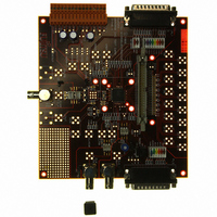
... Ordering Information The following reference should be used when ordering the customer development kit, • DK86060-3 Page Production Disclaimer: The contents of this document are subject to change without notice. Customers are advised to consult with FUJITSU sales representatives before ordering.The information and circuit diagrams in this document are presented “as is”, no license is granted by implication or otherwise. ...
Page 43
February 2009 Version 2.0 FME/MS/SFDAC1/DS/4250 MB86060 16-bit Interpolating Digital to Analog Converter Notes: Copyright © 2003-2009 Fujitsu Microelectronics Europe GmbH Disclaimer: The contents of this document are subject to change without notice. Customers are advised to consult with FUJITSU sales ...
Page 44
MB86060 16-bit Interpolating Digital to Analog Converter Worldwide Headquarters Japan Fujitsu Microelectronics Limited Tel: +81 3 5322 3347 Fax: +81 3 5322 3387 Shinjuku Dai-Ichi Seimei Bldg. 7-1, Nishishinjuku 2-chome Shinjuku-ku Tokyo 163-0722 Japan http://www.fujitsu.com/global/services/microelectronics/ USA Tel: +1 408 737 ...