DK86060-3 Fujitsu Semiconductor America Inc, DK86060-3 Datasheet - Page 11
DK86060-3
Manufacturer Part Number
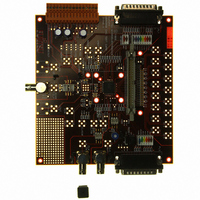
DK86060-3
Description
KIT DEV 16BIT DAC FOR MB86060
Manufacturer
Fujitsu Semiconductor America Inc
Specifications of DK86060-3
Number Of Dac's
1
Number Of Bits
16
Outputs And Type
1, Differential
Sampling Rate (per Second)
400M
Data Interface
Parallel
Dac Type
Current
Voltage Supply Source
Single
Operating Temperature
-40°C ~ 85°C
Utilized Ic / Part
MB86060
Lead Free Status / RoHS Status
Lead free / RoHS Compliant
Other names
865-1009


February 2009 Version 2.0
FME/MS/SFDAC1/DS/4250
MB86060 16-bit Interpolating Digital to Analog Converter
1.6.1
The DAC core incorporates a proprietary segment shuffling capability which is provided to further
improve linearity, and hence improve SFDR. This feature reduces any signal level dependent effects
on linearity as the same code can be generated by the same number of MSB cells but taken from
any quarter of the MSB segments. Segment shuffling can be selected to operate every 4, 8 or 16
updates of the DAC output using a random shuffle sequence between the four segments. Most
performance improvement will be observed when the device is used in one of the interpolating
modes. The effect of segment shuffling is to produce a spread noise spectrum, raising the overall
noise floor, but reducing the distortion. For minimum distortion when generating low frequency
signals, it is recommended that the shuffling clock rate is no more than 25MHz (F
Shuffling setting). See Table 7. However, low shuffle clock rates give reduced spreading out of
distortion components.
1.6.2
Within the front end digital processing there is no automatic protection against converter overload
except for clipping at 12-bit FSD. Warning of 12-bit overload at the input to the DAC is indicated by
a high logic level on the ‘OVER’ status pin. Conditions where care must be taken to avoid problems
due to overload would include input signal level when high levels of dither is selected, and fast edge
input data where inevitable overshoot in the digital filters occurs.
1.7
A 1.25V bandgap reference is provided on-chip, although this may be bypassed where an external
reference is to be used. To use the internal bandgap reference pins BGAP and VREF should be
linked via a 50
required. VREF should be decoupled to Reference Ground (RVSS) with a 100nF capacitor. For
maximum accuracy an external voltage reference is recommended
Copyright © 2003-2009 Fujitsu Microelectronics Europe GmbH
Disclaimer: The contents of this document are subject to change without notice. Customers are advised to consult with FUJITSU sales representatives before
Mode
0
1
2
3
Voltage Reference
ordering.The information and circuit diagrams in this document are presented “as is”, no license is granted by implication or otherwise.
Segment Shuffling
Converter Overload
SHUF1
0
0
1
1
resistor, or smaller if better rejection of reference noise at low frequencies is
SHUF0
0
1
0
1
Table 7: Segment Shuffling Control
Random - every 16 cycles
Random - every 4 cycles
Random - every 8 cycles
Segment Shuffling
Disabled
Production
100
F
200
DAC
Lowest noise
F
DAC
F
Note
100 MSa/s
DAC
200 MSa/s
MSa/s
DAC
/ Segment
Page 11 of 44
Related parts for DK86060-3
Image
Part Number
Description
Manufacturer
Datasheet
Request
R

Part Number:
Description:
IC POWER SUPPLY MONITOR 8SOP
Manufacturer:
Fujitsu Semiconductor America Inc
Datasheet:
Part Number:
Description:
IC POWER SUPPLY MONITOR 8SOP
Manufacturer:
Fujitsu Semiconductor America Inc
Datasheet:

Part Number:
Description:
IC MCU 60K FLASH 2KB RAM 52LQFP
Manufacturer:
Fujitsu Semiconductor America Inc
Datasheet:

Part Number:
Description:
IC MCU 32BIT 256KB FLASH 120LQFP
Manufacturer:
Fujitsu Semiconductor America Inc
Datasheet:
Part Number:
Description:
IC CTLR TOUCH SENSOR 12CH 30SSOP
Manufacturer:
Fujitsu Semiconductor America Inc
Datasheet:

Part Number:
Description:
IC CTLR TOUCH SENSOR 12CH 40QFN
Manufacturer:
Fujitsu Semiconductor America Inc
Datasheet:
Part Number:
Description:
SYNTHESIZER PLL DUAL INP 20SSOP
Manufacturer:
Fujitsu Semiconductor America Inc
Datasheet:

Part Number:
Description:
SYNTHESZR PLL 1.1GHZ DUAL 16SSOP
Manufacturer:
Fujitsu Semiconductor America Inc
Datasheet:

Part Number:
Description:
IC SSCG EMI RED 8-SOIC
Manufacturer:
Fujitsu Semiconductor America Inc
Datasheet:

Part Number:
Description:
IC SSCG EMI RED 8-TSSOP
Manufacturer:
Fujitsu Semiconductor America Inc
Datasheet:

Part Number:
Description:
IC SSCG EMI RED 8-SOP
Manufacturer:
Fujitsu Semiconductor America Inc
Datasheet:

Part Number:
Description:
SYNTHESIZER PLL 2.5GHZ 16SSOP
Manufacturer:
Fujitsu Semiconductor America Inc
Datasheet:
Part Number:
Description:
SYNTHESIZER PLL 1.2GHZ 16SSOP
Manufacturer:
Fujitsu Semiconductor America Inc
Datasheet:

Part Number:
Description:
SYNTHESIZER PLL 2.5GHZ 16BCC
Manufacturer:
Fujitsu Semiconductor America Inc
Datasheet:

Part Number:
Description:
IC SSCG EMI RED 8-SOP
Manufacturer:
Fujitsu Semiconductor America Inc
Datasheet: