SSL2102T/DB/FLYB120V,598 NXP Semiconductors, SSL2102T/DB/FLYB120V,598 Datasheet - Page 10
SSL2102T/DB/FLYB120V,598
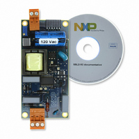
Manufacturer Part Number
SSL2102T/DB/FLYB120V,598
Description
KIT SSL2102 DESIGNER 120V
Manufacturer
NXP Semiconductors
Specifications of SSL2102T/DB/FLYB120V,598
Current - Output / Channel
400mA ~ 1.05A
Outputs And Type
1, Isolated
Voltage - Output
9 ~ 23 V
Features
Dimmable
Voltage - Input
85 ~ 276VAC
Utilized Ic / Part
SSL2102
Duty Cycle (max)
75 %
Mounting Style
SMD/SMT
Switching Frequency
100 KHz
Operating Supply Voltage
8.5 V to 40 V
Supply Current
1.7 A
Maximum Operating Temperature
+ 100 C
Minimum Operating Temperature
- 40 C
Output Power
1.6 W
Package / Case
SOIC-20
Lead Free Status / RoHS Status
Lead free / RoHS Compliant
Lead Free Status / RoHS Status
Lead free / RoHS Compliant, Lead free / RoHS Compliant
Other names
568-4931


NXP Semiconductors
UM10386
User manual
the LC filter within the dimmer. A serial resistor can be used for this for low power ranges
(<10 W) but for higher power ranges a single series resistor is not efficient. This is
because the converter supply current will cause significant voltage drop and thus
dissipation through this resistor. To improve efficiency, a combination of serial resistance
and a parallel damper has been chosen for the demonstration board. The serial resistor is
made up of F1, R1, R2 and R12 and the parallel damper comprises C2 and R3.
The input circuit of the converter must be equipped with a filter that is partially capacitive.
The combination of C1, L1, L2, C3 and C4 makes a filter that blocks most of the
disturbance generated by the converter input current. A drawback of this filter is a
reduction of power factor, due to the capacitive load. A lower converter power, in relation
to the capacitive value of this filter/buffer, will cause a lower power factor. The 230 V (AC)
design uses 150 nF capacitors, which attain a power factor of 0.9 for an 11 W output
power.
The board is equipped with a feedback loop that limits the output current. This feedback
loop senses the LED current over sense resistor R18 and a current mirror is used,
consisting of Q1 and Q2. The current level can be set using R20. The same feedback loop
is also used for overvoltage protection. If the LED voltage exceeds 23 V, a current will flow
through R19 and D9. The current through the opto-coupler IC2 will pull down the
PWMLIMIT and BRIGHTNESS pin. The on-time is zero at a value below 400 mV. The
feedback loop has proportional action only, and the gain is critical because of phase shift
caused by the converter and C6. The relationship between PWMLIMIT and output current
is quadratic in nature. The resultant output current spread will be acceptable for most LED
applications.
The dimming range is detected by sensing the average rectified voltage. R4, R5 and R17
comprise a voltage divider, and C9 filters the resultant signal. The converter sets its duty
factor and converter frequency accordingly.
All information provided in this document is subject to legal disclaimers.
Rev. 1 — 1 February 2011
SSL2102 19 W to 22 W mains dimmable LED driver
UM10386
© NXP B.V. 2011. All rights reserved.
10 of 24
Related parts for SSL2102T/DB/FLYB120V,598
Image
Part Number
Description
Manufacturer
Datasheet
Request
R

Part Number:
Description:
KIT SSL2102 DESIGNER 230V
Manufacturer:
NXP Semiconductors
Datasheet:

Part Number:
Description:
NXP Semiconductors designed the LPC2420/2460 microcontroller around a 16-bit/32-bitARM7TDMI-S CPU core with real-time debug interfaces that include both JTAG andembedded trace
Manufacturer:
NXP Semiconductors
Datasheet:

Part Number:
Description:
NXP Semiconductors designed the LPC2458 microcontroller around a 16-bit/32-bitARM7TDMI-S CPU core with real-time debug interfaces that include both JTAG andembedded trace
Manufacturer:
NXP Semiconductors
Datasheet:
Part Number:
Description:
NXP Semiconductors designed the LPC2468 microcontroller around a 16-bit/32-bitARM7TDMI-S CPU core with real-time debug interfaces that include both JTAG andembedded trace
Manufacturer:
NXP Semiconductors
Datasheet:
Part Number:
Description:
NXP Semiconductors designed the LPC2470 microcontroller, powered by theARM7TDMI-S core, to be a highly integrated microcontroller for a wide range ofapplications that require advanced communications and high quality graphic displays
Manufacturer:
NXP Semiconductors
Datasheet:
Part Number:
Description:
NXP Semiconductors designed the LPC2478 microcontroller, powered by theARM7TDMI-S core, to be a highly integrated microcontroller for a wide range ofapplications that require advanced communications and high quality graphic displays
Manufacturer:
NXP Semiconductors
Datasheet:
Part Number:
Description:
The Philips Semiconductors XA (eXtended Architecture) family of 16-bit single-chip microcontrollers is powerful enough to easily handle the requirements of high performance embedded applications, yet inexpensive enough to compete in the market for hi
Manufacturer:
NXP Semiconductors
Datasheet:
Part Number:
Description:
The XA-S3 device is a member of Philips Semiconductors? XA(eXtended Architecture) family of high performance 16-bitsingle-chip microcontrollers
Manufacturer:
NXP Semiconductors
Datasheet:

Part Number:
Description:
The NXP BlueStreak LH75401/LH75411 family consists of two low-cost 16/32-bit System-on-Chip (SoC) devices
Manufacturer:
NXP Semiconductors
Datasheet:
Part Number:
Description:
The NXP LPC3130/3131 combine an 180 MHz ARM926EJ-S CPU core, high-speed USB2
Manufacturer:
NXP Semiconductors
Datasheet:
Part Number:
Description:
The NXP LPC3141 combine a 270 MHz ARM926EJ-S CPU core, High-speed USB 2
Manufacturer:
NXP Semiconductors
Part Number:
Description:
The NXP LPC3143 combine a 270 MHz ARM926EJ-S CPU core, High-speed USB 2
Manufacturer:
NXP Semiconductors

Part Number:
Description:
The NXP LPC3152 combines an 180 MHz ARM926EJ-S CPU core, High-speed USB 2
Manufacturer:
NXP Semiconductors
Part Number:
Description:
The NXP LPC3154 combines an 180 MHz ARM926EJ-S CPU core, High-speed USB 2
Manufacturer:
NXP Semiconductors