NCP5006EVB ON Semiconductor, NCP5006EVB Datasheet - Page 15
NCP5006EVB
Manufacturer Part Number
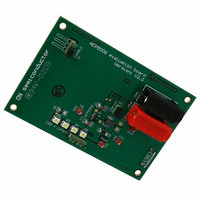
NCP5006EVB
Description
EVAL BOARD FOR NCP5006
Manufacturer
ON Semiconductor
Specifications of NCP5006EVB
Design Resources
NCP5006 Demo Board BOM NCP5006EVB Gerber Files NCP5006 Demo Board Schematic
Current - Output / Channel
15mA
Outputs And Type
1, Non-Isolated
Voltage - Output
22V
Voltage - Input
3.6V
Utilized Ic / Part
NCP5006
Core Chip
NCP5006
Topology
Boost
No. Of Outputs
1
Development Tool Type
Hardware - Eval/Demo Board
Mcu Supported Families
NCP5006
Lead Free Status / RoHS Status
Lead free / RoHS Compliant
Features
-
Lead Free Status / Rohs Status
Lead free / RoHS Compliant
For Use With/related Products
NCP5006
Other names
NCP5006EVBOS


TYPICAL APPLICATIONS CIRCUITS
Standard Feedback
LED, independently of the V
PWM Operation
LED by means of an external PWM signal as depicted in
Figure 29. By optimizing the internal high impedance
presented by the FB pin, one can set up a simple R/C
network to accommodate such a dimming function. Two
modes of operation can be considered:
•
•
function, from a human eye standpoint, it will continuously
The standard feedback provides a constant current to the
The analog feedback Pin 3 provides a way to dim the
Although the pulsed mode will provide a good dimming
Pulsed mode, with no filtering
Averaged mode with filtering capacitor
GND
Figure 28. Basic DC Current Mode Operation with Analog Feedback
bat
supply and number of LED
15 W
GND
R1
V
bat
LWT67C
4
2
3
D6
NCP5006
U1
EN
GND
FB
http://onsemi.com
LWT67C LWT67C LWT67C LWT67C
D5
V
V
NCP5006
bat
out
15
5
1
V
associated in series. Figure 28 depicts a typical application
to supply 13 mA to the load.
D4
start and stop the converter, yielding high transients . These
transients might generate spikes difficult to filter out in the
rest of the application, a situation not recommended. The
output current depends upon the duty cycle of the signal
presented to the node Pin 3: this is very similar to the digital
control discussed in Figure 31.
converter operates continuously, together with a very good
dimming function. The cost is an extra resistor and one
extra capacitor, both being low cost parts.
bat
The average mode yields a noise free operation since the
L1
22 mH
D3
MBR0530
4.7 mF
D1
C1
D2
GND
GND
C2
1.0 mF
Related parts for NCP5006EVB
Image
Part Number
Description
Manufacturer
Datasheet
Request
R

Part Number:
Description:
Compact Backlight LED Boost Driver
Manufacturer:
ON Semiconductor
Datasheet:
Part Number:
Description:
ON Semiconductor [VOLTAGE REGULATOR]
Manufacturer:
ON Semiconductor
Datasheet:
Part Number:
Description:
357-036-542-201 CARDEDGE 36POS DL .156 BLK LOPRO
Manufacturer:
ON Semiconductor
Datasheet:
Part Number:
Description:
357-036-542-201 CARDEDGE 36POS DL .156 BLK LOPRO
Manufacturer:
ON Semiconductor
Datasheet:
Part Number:
Description:
357-036-542-201 CARDEDGE 36POS DL .156 BLK LOPRO
Manufacturer:
ON Semiconductor
Datasheet:
Part Number:
Description:
357-036-542-201 CARDEDGE 36POS DL .156 BLK LOPRO
Manufacturer:
ON Semiconductor
Datasheet:
Part Number:
Description:
357-036-542-201 CARDEDGE 36POS DL .156 BLK LOPRO
Manufacturer:
ON Semiconductor
Datasheet:
Part Number:
Description:
357-036-542-201 CARDEDGE 36POS DL .156 BLK LOPRO
Manufacturer:
ON Semiconductor
Datasheet:
Part Number:
Description:
357-036-542-201 CARDEDGE 36POS DL .156 BLK LOPRO
Manufacturer:
ON Semiconductor
Datasheet:
Part Number:
Description:
357-036-542-201 CARDEDGE 36POS DL .156 BLK LOPRO
Manufacturer:
ON Semiconductor
Datasheet:
Part Number:
Description:
357-036-542-201 CARDEDGE 36POS DL .156 BLK LOPRO
Manufacturer:
ON Semiconductor
Datasheet:
Part Number:
Description:
357-036-542-201 CARDEDGE 36POS DL .156 BLK LOPRO
Manufacturer:
ON Semiconductor
Datasheet:
Part Number:
Description:
Manufacturer:
ON Semiconductor
Datasheet:
Part Number:
Description:
Manufacturer:
ON Semiconductor
Datasheet: