NCP5005GEVB ON Semiconductor, NCP5005GEVB Datasheet - Page 9
NCP5005GEVB
Manufacturer Part Number
NCP5005GEVB
Description
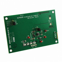
EVAL BOARD FOR NCP5005G
Manufacturer
ON Semiconductor
Specifications of NCP5005GEVB
Design Resources
NCP5005 EVB BOM NCP5005GEVB Gerber Files NCP5005 EVB Schematic
Outputs And Type
1, Non-Isolated
Voltage - Output
22V
Voltage - Input
3.6V
Utilized Ic / Part
NCP5005
Core Chip
NCP5005
Topology
Boost
No. Of Outputs
1
Development Tool Type
Hardware - Eval/Demo Board
Leaded Process Compatible
Yes
Mcu Supported Families
NCP5005SNT1G
Rohs Compliant
Yes
Lead Free Status / RoHS Status
Lead free / RoHS Compliant
Features
-
Current - Output / Channel
-
Lead Free Status / Rohs Status
Lead free / RoHS Compliant
For Use With/related Products
NCP5005G
Other names
NCP5005GEVBOS


Output Load Drive
shall operate the NCP5005 in the continuous output current
mode. Such a mode is achieved by using and external
reservoir capacitor (see Table 1) across the LED.
diodes shall be within the maximum ratings specified for
these devices. Of course, pulsed operation can be achieved,
due to the EN signal Pin 4, to force high current into the
LED when necessary.
100
100
In order to optimize the built−in Boost capabilities, one
At this point, the peak current flowing into the LED
90
80
70
60
50
40
30
20
10
90
80
70
60
50
40
30
20
10
0
0
2.50
2.50
Figure 10. Overall Efficiency vs. Power Supply @
Figure 12. Overall Efficiency vs. Power Supply @
4 LED/15 mA
5 LED/4 mA
3 LED/15 mA
Yield = f(V
Yield = f(V
3.00
3.00
5 LED/15 mA
3 LED/4 mA
I
out
bat
I
bat
out
3.50
3.50
) @ I
) @ I
= 4.0 mA, L = 22 mH
= 15 mA, L = 22 mH
out
4 LED/4 mA
out
V
Vbat (V)
bat
4.00
4.00
= 4.0 mA/L
= 15 mA/L
(V)
2 LED/4 mA
TYPICAL OPERATING CHARACTERISTICS
4.50
4.50
2 LED/15 mA
out
out
= 22 mH
= 22 mH
5.00
5.00
http://onsemi.com
5.50
5.50
NCP5005
9
(see Figure 9), provides a rectification and filtering
function.
•
100
100
90
80
70
60
50
40
30
20
10
90
80
70
60
50
40
30
20
10
The Schottky diode D1, associated with capacitor C2
When a pulse−operating mode is acceptable:
A PWM mode control can be used to adjust the output
current range by means of a resistor and a capacitor
connected across FB pin. On the other hand, the
Schottky diode can be removed and replaced by at
least one LED diode, keeping in mind such LED shall
sustain the large pulsed peak current during the
operation.
0
0
2.50
2.50
Figure 11. Overall Efficiency vs. Power Supply @
Figure 13. Overall Efficiency vs. Power Supply @
4 LED/20 mA
2 LED/10 mA
3 LED/20 mA
Yield = f(V
Yield = f(V
3.00
3.00
4 LED/10 mA
5 LED/20 mA
I
out
I
bat
bat
out
3.50
3.50
) @ I
= 10 mA, L = 22 mH
) @ I
= 20 mA, L = 22 mH
5 LED/10 mA
out
out
V
Vbat (V)
bat
4.00
4.00
= 10 mA/L
= 20 mA/L
(V)
4.50
4.50
2 LED/20 mA
3 LED/10 mA
out
out
= 22 mH
= 22 mH
5.00
5.00
5.50
5.50
Related parts for NCP5005GEVB
Image
Part Number
Description
Manufacturer
Datasheet
Request
R

Part Number:
Description:
Compact Backlight LED Boost Driver
Manufacturer:
ON Semiconductor
Datasheet:
Part Number:
Description:
ON Semiconductor [VOLTAGE REGULATOR]
Manufacturer:
ON Semiconductor
Datasheet:
Part Number:
Description:
357-036-542-201 CARDEDGE 36POS DL .156 BLK LOPRO
Manufacturer:
ON Semiconductor
Datasheet:
Part Number:
Description:
357-036-542-201 CARDEDGE 36POS DL .156 BLK LOPRO
Manufacturer:
ON Semiconductor
Datasheet:
Part Number:
Description:
357-036-542-201 CARDEDGE 36POS DL .156 BLK LOPRO
Manufacturer:
ON Semiconductor
Datasheet:
Part Number:
Description:
357-036-542-201 CARDEDGE 36POS DL .156 BLK LOPRO
Manufacturer:
ON Semiconductor
Datasheet:
Part Number:
Description:
357-036-542-201 CARDEDGE 36POS DL .156 BLK LOPRO
Manufacturer:
ON Semiconductor
Datasheet:
Part Number:
Description:
357-036-542-201 CARDEDGE 36POS DL .156 BLK LOPRO
Manufacturer:
ON Semiconductor
Datasheet:
Part Number:
Description:
357-036-542-201 CARDEDGE 36POS DL .156 BLK LOPRO
Manufacturer:
ON Semiconductor
Datasheet:
Part Number:
Description:
357-036-542-201 CARDEDGE 36POS DL .156 BLK LOPRO
Manufacturer:
ON Semiconductor
Datasheet:
Part Number:
Description:
357-036-542-201 CARDEDGE 36POS DL .156 BLK LOPRO
Manufacturer:
ON Semiconductor
Datasheet:
Part Number:
Description:
357-036-542-201 CARDEDGE 36POS DL .156 BLK LOPRO
Manufacturer:
ON Semiconductor
Datasheet:
Part Number:
Description:
Manufacturer:
ON Semiconductor
Datasheet:
Part Number:
Description:
Manufacturer:
ON Semiconductor
Datasheet: