MCP651EV-VOS Microchip Technology, MCP651EV-VOS Datasheet - Page 29
MCP651EV-VOS
Manufacturer Part Number
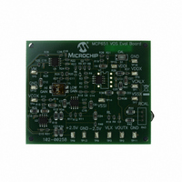
MCP651EV-VOS
Description
BOARD EVAL OP AMP MCP651
Manufacturer
Microchip Technology
Series
mCal Technologyr
Specifications of MCP651EV-VOS
Channels Per Ic
1 - Single
Amplifier Type
General Purpose
Output Type
Single-Ended, Rail-to-Rail
Slew Rate
30 V/µs
Current - Output / Channel
100mA
Operating Temperature
-40°C ~ 125°C
Current - Supply (main Ic)
6mA
Voltage - Supply, Single/dual (±)
2.5 V ~ 5.5 V
Board Type
Fully Populated
Utilized Ic / Part
MCP651
Processor To Be Evaluated
MCP651
Maximum Operating Temperature
+ 125 C
Minimum Operating Temperature
- 40 C
Operating Supply Voltage
2.5 V to 5.5 V
Tool Type
Evaluation Board
Core Architecture
PIC
Cpu Core
PIC
Data Bus Width
8 bit
Lead Free Status / RoHS Status
Lead free / RoHS Compliant
-3db Bandwidth
-
Lead Free Status / Rohs Status
Lead free / RoHS Compliant
Available stocks
Company
Part Number
Manufacturer
Quantity
Price
Company:

Part Number:
MCP651EV-VOS
Manufacturer:
Microchip Technology
Quantity:
135
Company:
Part Number:
MCP651EV-VOS
Manufacturer:
MICROCHIP
Quantity:
12 000


A.1
A.2
© 2009 Microchip Technology Inc.
INTRODUCTION
SCHEMATIC AND LAYOUTS
This appendix contains the schematics and layouts for the MCP651 Input Offset
Evaluation Board.
See A.3 “Board – Schematic” for the circuit diagram. U1 is the DUT (MCP651). U2
buffers the attenuated and filtered control voltage VCOX. U3 is the differential
integrator. U4 is the amplifier that gives the final gain to the DUT’s input offset voltage
(V
DUT. Switch S2 makes it so the amplifier (U4) can have two different gains, providing
a tradeoff between accuracy and range.
A.4 “Board – Combination of the Top Silk-Screen, Top Solder Mask and Top Metal
Layers” through A.7 “Board – Bottom Metal Layer” show the PCB layout plots. This
PCB has two metal layers: signal and power traces on top and ground plane on bottom.
Groups of critical resistors have been arranged so that their thermoelectric voltages
cancel (assuming constant temperature gradient); these groups are:
• R
• R
• R
• R
• R
The Gerber files for this board are available on the Microchip website
(www.microchip.com) and are contained in the zip file “00258R2_Gerbers.zip”.
Appendix A. Schematics and Layouts
OST
1
5
7
21
24
through R
and R
and R
). Switch S1 gives the user a means of starting an auto-calibration cycle in the
through R
and R
6
8
25
4
23
MCP651 INPUT OFFSET
EVALUATION BOARD
USER’S GUIDE
DS51834A-page 25
Related parts for MCP651EV-VOS
Image
Part Number
Description
Manufacturer
Datasheet
Request
R

Part Number:
Description:
Manufacturer:
Microchip Technology Inc.
Datasheet:
Part Number:
Description:
Manufacturer:
Microchip Technology Inc.
Datasheet:
Part Number:
Description:
Manufacturer:
Microchip Technology Inc.
Datasheet:
Part Number:
Description:
Manufacturer:
Microchip Technology Inc.
Datasheet:
Part Number:
Description:
Manufacturer:
Microchip Technology Inc.
Datasheet:
Part Number:
Description:
Manufacturer:
Microchip Technology Inc.
Datasheet:
Part Number:
Description:
Manufacturer:
Microchip Technology Inc.
Datasheet:
Part Number:
Description:
Manufacturer:
Microchip Technology Inc.
Datasheet: