SCC1300-D04DEMO VTI Technologies, SCC1300-D04DEMO Datasheet - Page 10
SCC1300-D04DEMO
Manufacturer Part Number
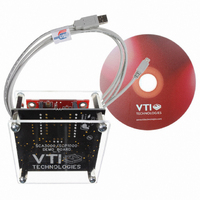
SCC1300-D04DEMO
Description
DEMO KIT WITH SCC1300-D04
Manufacturer
VTI Technologies
Datasheet
1.SCC1300-D04_PWB.pdf
(30 pages)
Specifications of SCC1300-D04DEMO
Sensor Type
Accelerometer, Gyroscope, 3 Axis
Sensing Range
±6g;, ±300°/sec
Interface
SPI
Sensitivity
Gyro: 18 LSB/(°/s), ±0.1 (°/s)/g Accel: 650LSB/g
Embedded
No
Utilized Ic / Part
SCC1300-D04
Lead Free Status / RoHS Status
Lead free / RoHS Compliant
Voltage - Supply
-
Other names
551-1070
SCC1300-D02DEMO
SCC1300-D02DEMO


3
3.1 Power-up Sequence for Gyroscope
Table 7. SCC1300 gyroscope power-up sequence.
3.2 Start-up and Operation Sequence for Accelerometer
3.2.1 Recommended Start-up Sequence
Table 8. SCC1300 accelerometer part start-up sequence.
VTI Technologies Oy
www.vti.fi
Procedure
Set V
Wait 10ms
Set V
Wait 800 ms
Read Status register (08h) two times
Procedure
Set Vdd=3.0...3.6V
Wait 35ms
Read INT_STATUS
Write CTRL=00001010 (a)
or
or
Wait 10ms
Read CTRL
Read Z_MSB, Z_LSB, Y_MSB, Y_LSB,
X_MSB, X_LSB
Reset and Power Up
DVDD_G
AVDD_G
CTRL=00001000 (b)
CTRL=00000000 (c)
V=3.0...3.6V
V=4.75...5.25V
After the start-up the angular rate and acceleration data is immediately available through SPI
registers. There is no need to initialize the gyroscope or accelerometer before starting to use it. If
the application requires monitoring operation correctness there are several options available to
monitor the status.
To ensure correct ASIC start up please connect the digital supply voltage V
analog supply voltage V
twice to clear error flags. Angular rate data is available immediately so no start up command
sequence is required if error flags are not used.
For correct device operation there are no specific configuration needed for the device before
starting of measuring the acceleration. However if the device diagnostic features are being used
the following operations could be made after the powering on the device.
AVDD_G
Doc.Nr. 82 1131 00 A
Subject to changes
Functions
Acknowledge error flags after start up
Functions
Release part from reset
Memory reading and self-diagnostic
Settling of signal path
Acknowledge for possible saturation (SAT-bit)
Checksum pass detected from SPI frame
Set PORST=0 (abc)
Start STC (ab)
Start STS (a)
STS calculation
Check that STC is on, if enabled
Check that STS is over if enabled
Read acceleration data
(5.0V) to the gyro ASIC. After power up please read Status register
Check
Check
SPI fixed bits
SPI ST=0
SPI fixed bits
SPI FRME=0
SPI ST=0
SPI SAT=0
CTRL.ST=1
CTRL.ST_CFG=0
SPI fixed bits
SPI FRME=0
SPI PORST=0
SPI ST=0
SPI SAT=0
dPAR, data parity
SPI fixed bits
SPI FRME=0
SPI PORST=0
SPI ST=0
SPI SAT=0
dPAR, data parity
DVDD_G
(3.3V) before the
SCC1300-D04
Rev. 1.0
10/30
Related parts for SCC1300-D04DEMO
Image
Part Number
Description
Manufacturer
Datasheet
Request
R

Part Number:
Description:
GYRO/ACC COMBO 3-AXIS +/-2G SPI
Manufacturer:
VTI Technologies
Datasheet:

Part Number:
Description:
GYRO/ACC COMBO 3-AXIS +/-6G SPI
Manufacturer:
VTI Technologies
Datasheet:

Part Number:
Description:
ACCELEROMETER SGL 1.7G DIL8 SMD
Manufacturer:
VTI Technologies
Datasheet:

Part Number:
Description:
VTI Automotive Digital Accelerometer Platform
Manufacturer:
VTI [VTI technologies]
Datasheet:

Part Number:
Description:
BOARD PWB ACCEL 3-AXIS SPI/I2C
Manufacturer:
VTI Technologies
Datasheet:

Part Number:
Description:
EVAL BOARD ACCELEROMETER Y-AXIS
Manufacturer:
VTI Technologies
Datasheet:

Part Number:
Description:
EVAL BOARD INCLINOMETER Y-AXIS
Manufacturer:
VTI Technologies
Datasheet:

Part Number:
Description:
KIT DEMO ACCELEROMTR CMA3000-D01
Manufacturer:
VTI Technologies
Datasheet:

Part Number:
Description:
KIT DEMO ACCELEROMTR SCA3060-D01
Manufacturer:
VTI Technologies
Datasheet:

Part Number:
Description:
BOARD PWB ACCEL 3AXIS ANALG OUT
Manufacturer:
VTI Technologies
Datasheet:
Part Number:
Description:
ACCELEROMETER SGL 1.7G DIL8 SMD
Manufacturer:
VTI Technologies
Datasheet:
Part Number:
Description:
VTI Automotive Digital Accelerometer Platform
Manufacturer:
VTI [VTI technologies]
Datasheet:
Part Number:
Description:
Accelerometer
Manufacturer:
VTI [VTI technologies]
Datasheet:
Part Number:
Description:
Stand Alone Inclinometer
Manufacturer:
VTI [VTI technologies]
Datasheet:
Part Number:
Description:
3-axis accelerometer
Manufacturer:
VTI [VTI technologies]
Datasheet: