SCC1300-D04DEMO VTI Technologies, SCC1300-D04DEMO Datasheet - Page 20
SCC1300-D04DEMO
Manufacturer Part Number
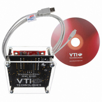
SCC1300-D04DEMO
Description
DEMO KIT WITH SCC1300-D04
Manufacturer
VTI Technologies
Datasheet
1.SCC1300-D04_PWB.pdf
(30 pages)
Specifications of SCC1300-D04DEMO
Sensor Type
Accelerometer, Gyroscope, 3 Axis
Sensing Range
±6g;, ±300°/sec
Interface
SPI
Sensitivity
Gyro: 18 LSB/(°/s), ±0.1 (°/s)/g Accel: 650LSB/g
Embedded
No
Utilized Ic / Part
SCC1300-D04
Lead Free Status / RoHS Status
Lead free / RoHS Compliant
Voltage - Supply
-
Other names
551-1070
SCC1300-D02DEMO
SCC1300-D02DEMO


4.5
4.5.1 Register Map of Accelerometer
Table 14. Register address space
VTI Technologies Oy
www.vti.fi
Address
Dec (hex)
00(00)
01(01)
02(02)
02(02)
02(02)
02(02)
03(03)
04(04)
04(04)
05(05)
05(05)
06(06)
06(06)
07(07)
07(07)
08(08)
08(08)
09(09)
09(09)
12(0C)
13(0D)
16(10)
16(10)
16(10)
16(10)
16(10)
27(1B)
Accelerometer ASIC Addressing Space
The SCC1300 register contents and bit definitions are described in detail in the following sections.
Note: The acceleration data is presented in 2's complement format. At 0 g acceleration the output is ideally 0000h.
Note: INT_STATUS: The bits in this interrupt status register and corresponding SPI frame bits are cleared after register has
been read. Register reading is treated as interrupt acknowledgement signal. These bits are kept active even failure
condition is over if they are not acknowledged.
Register Name
[bit definition]
REVID
CTRL
STATUS [7:3]
STATUS [2]
(ATEST)
STATUS [1]
(CSMERR)
STATUS [1]
(FRME)
RESET
X_LSB [7:2]
X_LSB [1:0]
X_MSB [6:0]
X_MSB [7]
Y_LSB [7:2]
Y_LSB [1:0]
Y_MSB [6:0]
Y_MSB [7]
Z_LSB [7:2]
Y_LSB [1:0]
Z_MSB [6:0]
Z_MSB [7]
TEMP_LSB
TEMP_MSB
INT_STATUS [7]
INT_STATUS [6]
(SAT)
INT_STATUS [5]
(STS)
INT_STATUS [4]
(STC)
INT_STATUS [3:0]
ID
Number
of Bits
8
8
5
1
1
1
8
6
2
7
1
6
2
7
1
6
2
7
1
8
8
1
1
8
Doc.Nr. 82 1131 00 A
Subject to changes
Read/
Write
R/W
R/W
R
R
R
R
R
R
R
R
R
R
R
R
R
R
R
R
R
R
R
R
Data format
-
-
-
See chapter
4.5.3.
See chapter
4.5.3.
Description
ASIC revision identification number, each ASIC version has
different REVID-number.
Please refer to chapter 4.5.2 for CONTROL register details.
Reserved
Analog test mode status
1 – Test mode is active
0 – Test mode is not active
EEPROM Checksum Error. ST bit of SPI frame is also set if
CSMERR is set.
SPI frame error. Bit is reset, when next correct SPI frame is
received. Bit is also visible in SPI frame.
Writing 0C'hex, 05'hex, 0F'hex in this order resets component.
X-axis LSB data frame (Read always X_MSB prior to X_LSB)
Reserved
X-axis MSB data bits (Reading of this register latches X_LSB)
Reserved
Y-axis LSB data frame (Read always Y_MSB prior to Y_LSB)
Reserved
Y-axis MSB data bits (Reading of this register latches Y_LSB)
Reserved
Z-axis LSB data frame (Read Z_MSB prior to Z_LSB)
Reserved
Z-axis MSB data bits (Reading of this register latches Z_LSB)
Reserved
Data bits [7:0] of temperature sensor.
Read always TEMP_MSB prior to TEMP_LSB.
Data bits [15:8] of temperature sensor.
Reading of this register latches TEMP_LSB.
Reserved
Saturation status of output data
1 – Over range detected, one or 2-3 of xyz axis is saturated
and output data is not valid.
0 – Data in range
SAT bit is also visible in SPI frame. This bit can be active after
start-up or reset stage before signal path settles to final value
and it has to be acknowledged in start-up sequence (see
Table 8) or after SW reset or after PORST stage.
Status of gravitation based start-up self test
1 – Failure
0 – No failure
STS sets also ST bit in SPI frame.
Status of continuous self test
1 – Failure
0 – No failure
STC sets also ST bit in SPI frame.
Reserved
Component identification number
possible to this register but not to non-volatile memory)
(write operation by user is
SCC1300-D04
Rev. 1.0
20/30
Related parts for SCC1300-D04DEMO
Image
Part Number
Description
Manufacturer
Datasheet
Request
R

Part Number:
Description:
GYRO/ACC COMBO 3-AXIS +/-2G SPI
Manufacturer:
VTI Technologies
Datasheet:

Part Number:
Description:
GYRO/ACC COMBO 3-AXIS +/-6G SPI
Manufacturer:
VTI Technologies
Datasheet:

Part Number:
Description:
ACCELEROMETER SGL 1.7G DIL8 SMD
Manufacturer:
VTI Technologies
Datasheet:

Part Number:
Description:
VTI Automotive Digital Accelerometer Platform
Manufacturer:
VTI [VTI technologies]
Datasheet:

Part Number:
Description:
BOARD PWB ACCEL 3-AXIS SPI/I2C
Manufacturer:
VTI Technologies
Datasheet:

Part Number:
Description:
EVAL BOARD ACCELEROMETER Y-AXIS
Manufacturer:
VTI Technologies
Datasheet:

Part Number:
Description:
EVAL BOARD INCLINOMETER Y-AXIS
Manufacturer:
VTI Technologies
Datasheet:

Part Number:
Description:
KIT DEMO ACCELEROMTR CMA3000-D01
Manufacturer:
VTI Technologies
Datasheet:

Part Number:
Description:
KIT DEMO ACCELEROMTR SCA3060-D01
Manufacturer:
VTI Technologies
Datasheet:

Part Number:
Description:
BOARD PWB ACCEL 3AXIS ANALG OUT
Manufacturer:
VTI Technologies
Datasheet:
Part Number:
Description:
ACCELEROMETER SGL 1.7G DIL8 SMD
Manufacturer:
VTI Technologies
Datasheet:
Part Number:
Description:
VTI Automotive Digital Accelerometer Platform
Manufacturer:
VTI [VTI technologies]
Datasheet:
Part Number:
Description:
Accelerometer
Manufacturer:
VTI [VTI technologies]
Datasheet:
Part Number:
Description:
Stand Alone Inclinometer
Manufacturer:
VTI [VTI technologies]
Datasheet:
Part Number:
Description:
3-axis accelerometer
Manufacturer:
VTI [VTI technologies]
Datasheet: