SCC1300-D04DEMO VTI Technologies, SCC1300-D04DEMO Datasheet - Page 21
SCC1300-D04DEMO
Manufacturer Part Number
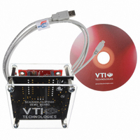
SCC1300-D04DEMO
Description
DEMO KIT WITH SCC1300-D04
Manufacturer
VTI Technologies
Datasheet
1.SCC1300-D04_PWB.pdf
(30 pages)
Specifications of SCC1300-D04DEMO
Sensor Type
Accelerometer, Gyroscope, 3 Axis
Sensing Range
±6g;, ±300°/sec
Interface
SPI
Sensitivity
Gyro: 18 LSB/(°/s), ±0.1 (°/s)/g Accel: 650LSB/g
Embedded
No
Utilized Ic / Part
SCC1300-D04
Lead Free Status / RoHS Status
Lead free / RoHS Compliant
Voltage - Supply
-
Other names
551-1070
SCC1300-D02DEMO
SCC1300-D02DEMO


4.5.2
Table 15. SCC1300 accelerometer ASIC control register bit level description.
4.5.3
Table 16 Bit level description for accelerometer temperature registers
x = not used bit
r=reserved
VTI Technologies Oy
www.vti.fi
Register
Bit number
Bit in temperature register
Bits
7
6
5
4
3
2
1
0
Control Register (CTRL)
Temperature Output Registers
Mode
RW
RW
RW
RW
RW
RW
RW
RW
Temp
The offset of temperature data is factory calibrated but sensitivity of the temperature data varies
from part to part. Temperature data is in unsigned format and 13 bits (13:1) of
TEMP_MSB/TEMP_LSB are used for temperature. Here is presented temperature calculation
using 10bit but 3-extra LSB bit can be used to improve resolution in noise sense if needed.
Temperature registers’ typical output at +23 °C is 512 counts and 1 °C change in temperature
typically corresponds to 3.2 LSB change in temperature output. Temperature information is
converted to [°C] as follows
where Temp[°C] is temperature in Celsius and Temp
TEMP_LSB registers in decimal format, bits(t9:0). k is temperature slope factor specified as
k
Initial
Value
0
0
0
0
0
0
0
0
[ ] (
°
C
=
Min
2.8
Name
PORST
PDOW
SLEEP
ST
MST
ST_CFG
MISO
23
±
10
)
°
C
Typ
3.2
Doc.Nr. 82 1131 00 A
Subject to changes
Description
Reserved
1 means reset state. Bit gets set to 1 when the digital gets reset by supply off control or
under voltage control. Bit is set after supply off/on transition or startup. This bit can not be
set by SPI but it can be reset to 0 by writing a 0 over the SPI. This bit is also sent as Bit3
of SPI output data frame on MISO.
Set chip to power down mode
Set chip to sleep mode. This bit can not be set to 1 if PDOW is already 1 or if PDOW is
being set by the current SPI command.
Set chip to self-test mode. Start continuous self-test calculation (STC). This bit can not
be set to 1 if PDOW or SLEEP or MTST is already 1 or if PDOW or SLEEP or MTST is
being set by the current SPI command. Use INT_STATUS.STC and ST bit of SPI frame
for test result monitoring.
Memory self-test function is activated, when user sets bit to ‘1’. This bit is reset to 0 when
test is over. During memory self test, SPI access is prevented for 85us. This bit can not
be set to 1 if PDOW or SLEEP is already 1 or if PDOW or SLEEP is being set by the
current SPI command. Test is done automatically during start-up. Set other bits to zero in
CTRL register by previous SPI command before starting memory self-test by CTRL.MST
command. Use STATUS.CSMERR for test result monitoring and ST bit in SPI frame.
Self-test configuration. Start gravitation based start-up self-test calculation (STS). This bit
can not be set to 1 if PDOW or SLEEP or MTST is already 1 or if PDOW or SLEEP or
MTST is being set by the current SPI command. STC and STS have same priority and
they can be set and used simultaneously. This bit is set to 0 when test is over. Use
INT_STATUS.STS and ST bit of SPI frame for test result monitoring.
0 = Set MISO line to normal state (= High impedance state between SPI transfers, data
out state during transfers)
1 = Set MISO like to a continuous high impedance state (same write command to
multiple slaves, which share MISO line).
TEMP_MSB
B7:B6
xx
+
Temp
dec
k
Max
3.6
B5 B4 B3 B2 B1 B0 B7 B6 B5 B4 B3:B1 B0
t9
LSB
−
°
C
512
t8
LSB
t7
,
Unit
LSB/
T6
dec
o
C
is temperature from TEMP_MSB and
T5
t4
TEMP_LSB
t3
t2
t1
t0
r r r
SCC1300-D04
x
Rev. 1.0
21/30
Related parts for SCC1300-D04DEMO
Image
Part Number
Description
Manufacturer
Datasheet
Request
R

Part Number:
Description:
GYRO/ACC COMBO 3-AXIS +/-2G SPI
Manufacturer:
VTI Technologies
Datasheet:

Part Number:
Description:
GYRO/ACC COMBO 3-AXIS +/-6G SPI
Manufacturer:
VTI Technologies
Datasheet:

Part Number:
Description:
ACCELEROMETER SGL 1.7G DIL8 SMD
Manufacturer:
VTI Technologies
Datasheet:

Part Number:
Description:
VTI Automotive Digital Accelerometer Platform
Manufacturer:
VTI [VTI technologies]
Datasheet:

Part Number:
Description:
BOARD PWB ACCEL 3-AXIS SPI/I2C
Manufacturer:
VTI Technologies
Datasheet:

Part Number:
Description:
EVAL BOARD ACCELEROMETER Y-AXIS
Manufacturer:
VTI Technologies
Datasheet:

Part Number:
Description:
EVAL BOARD INCLINOMETER Y-AXIS
Manufacturer:
VTI Technologies
Datasheet:

Part Number:
Description:
KIT DEMO ACCELEROMTR CMA3000-D01
Manufacturer:
VTI Technologies
Datasheet:

Part Number:
Description:
KIT DEMO ACCELEROMTR SCA3060-D01
Manufacturer:
VTI Technologies
Datasheet:

Part Number:
Description:
BOARD PWB ACCEL 3AXIS ANALG OUT
Manufacturer:
VTI Technologies
Datasheet:
Part Number:
Description:
ACCELEROMETER SGL 1.7G DIL8 SMD
Manufacturer:
VTI Technologies
Datasheet:
Part Number:
Description:
VTI Automotive Digital Accelerometer Platform
Manufacturer:
VTI [VTI technologies]
Datasheet:
Part Number:
Description:
Accelerometer
Manufacturer:
VTI [VTI technologies]
Datasheet:
Part Number:
Description:
Stand Alone Inclinometer
Manufacturer:
VTI [VTI technologies]
Datasheet:
Part Number:
Description:
3-axis accelerometer
Manufacturer:
VTI [VTI technologies]
Datasheet: