Z8F16800128ZCOG Zilog, Z8F16800128ZCOG Datasheet - Page 213
Z8F16800128ZCOG
Manufacturer Part Number
Z8F16800128ZCOG
Description
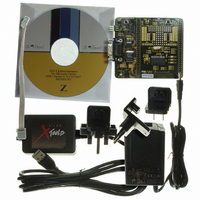
KIT DEV FOR Z8F642 MCU 28PIN
Manufacturer
Zilog
Series
Z8 Encore!®r
Type
MCUr
Datasheets
1.Z8F16800128ZCOG.pdf
(399 pages)
2.Z8F16800128ZCOG.pdf
(3 pages)
3.Z8F16800128ZCOG.pdf
(564 pages)
Specifications of Z8F16800128ZCOG
Contents
Hardware, Software and Documentation
Processor To Be Evaluated
F083A
Data Bus Width
8 bit
Interface Type
RS-232, USB
For Use With/related Products
Z8F642
For Use With
269-4661 - KIT ACC ETHERNET SMART CABLE
Lead Free Status / RoHS Status
Lead free / RoHS Compliant
Other names
269-4677


®
Z8 Encore! XP
F1680 Series
Product Specification
199
Synchronous Frame Sync Pulse Mode
This mode is selected by setting the SSMD field of the Mode Register to 10. This mode is
typically used for continuous transfer of fixed length frames where the frames are
delineated by a pulse of duration one SCK period. The SSV bit in the ESPI Transmit Data
Command register does not control the SS pin directly in this mode. SSV must be set
before or in sync with the first transmit data byte being written. The SS signal will assert 1
SCK cycle before the first data bit and will stop after 1 SCK period. SCK is active from
the initial assertion of SS until the transaction end due to lack of transmit data.
The transaction is terminated by the Master when it no longer has data to send. If
TDRE=1 at the end of a character, the SS output will remain detached and SCK stops after
the last bit is transferred. The TUND bit (transmit underrun) will assert in this case. Once
the transaction has completed, hardware will clear the SSV bit.
Figure 37
displays a frame
with synchronous frame sync pulse mode.
SCK (SSMD = 10,
PHASE = 0,
CLKPOL = 0,
SSPO = 1)
Bit7
Bit6
Bit1
Bit0
Bit7
Bit 6
MOSI, MISO
SS
SSV
Figure 37. Synchronous Frame Sync Pulse mode (SSMD = 10)
Synchronous Framing with SS Mode
This mode is selected by setting the SSMD field of the Mode Register to 11.
Figure 38
on
page 200 displays synchronous message framing mode with SS alternating between
consecutive frames. A frame consists of a fixed number of data bytes as defined by
2
software. An example of this mode is the Inter-IC Sound (I
S) protocol which is used to
transfer left/right channel audio data. The SSV indicates whether the corresponding bytes
are left or right channel data. The SSV value must be updated when servicing the
TDRE interrupt/request for the first byte in a left or write channel frame. This can be
PS025011-1010
P R E L I M I N A R Y
Enhanced Serial Peripheral Interface
Related parts for Z8F16800128ZCOG
Image
Part Number
Description
Manufacturer
Datasheet
Request
R

Part Number:
Description:
Communication Controllers, ZILOG INTELLIGENT PERIPHERAL CONTROLLER (ZIP)
Manufacturer:
Zilog, Inc.
Datasheet:

Part Number:
Description:
KIT DEV FOR Z8 ENCORE 16K TO 64K
Manufacturer:
Zilog
Datasheet:

Part Number:
Description:
KIT DEV Z8 ENCORE XP 28-PIN
Manufacturer:
Zilog
Datasheet:

Part Number:
Description:
DEV KIT FOR Z8 ENCORE 8K/4K
Manufacturer:
Zilog
Datasheet:

Part Number:
Description:
KIT DEV Z8 ENCORE XP 28-PIN
Manufacturer:
Zilog
Datasheet:

Part Number:
Description:
DEV KIT FOR Z8 ENCORE 4K TO 8K
Manufacturer:
Zilog
Datasheet:
Part Number:
Description:
CMOS Z8 microcontroller. ROM 16 Kbytes, RAM 256 bytes, speed 16 MHz, 32 lines I/O, 3.0V to 5.5V
Manufacturer:
Zilog, Inc.
Datasheet:
Part Number:
Description:
Low-cost microcontroller. 512 bytes ROM, 61 bytes RAM, 8 MHz
Manufacturer:
Zilog, Inc.
Datasheet:
Part Number:
Description:
Z8 4K OTP Microcontroller
Manufacturer:
Zilog, Inc.
Datasheet:
Part Number:
Description:
CMOS SUPER8 ROMLESS MCU
Manufacturer:
Zilog, Inc.
Datasheet:
Part Number:
Description:
SL1866 CMOSZ8 OTP Microcontroller
Manufacturer:
Zilog, Inc.
Datasheet:
Part Number:
Description:
SL1866 CMOSZ8 OTP Microcontroller
Manufacturer:
Zilog, Inc.
Datasheet:
Part Number:
Description:
OTP (KB) = 1, RAM = 125, Speed = 12, I/O = 14, 8-bit Timers = 2, Comm Interfaces Other Features = Por, LV Protect, Voltage = 4.5-5.5V
Manufacturer:
Zilog, Inc.
Datasheet:
Part Number:
Description:
Manufacturer:
Zilog, Inc.
Datasheet: