Z8F16800128ZCOG Zilog, Z8F16800128ZCOG Datasheet - Page 221
Z8F16800128ZCOG
Manufacturer Part Number
Z8F16800128ZCOG
Description
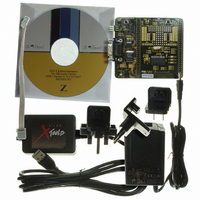
KIT DEV FOR Z8F642 MCU 28PIN
Manufacturer
Zilog
Series
Z8 Encore!®r
Type
MCUr
Datasheets
1.Z8F16800128ZCOG.pdf
(399 pages)
2.Z8F16800128ZCOG.pdf
(3 pages)
3.Z8F16800128ZCOG.pdf
(564 pages)
Specifications of Z8F16800128ZCOG
Contents
Hardware, Software and Documentation
Processor To Be Evaluated
F083A
Data Bus Width
8 bit
Interface Type
RS-232, USB
For Use With/related Products
Z8F642
For Use With
269-4661 - KIT ACC ETHERNET SMART CABLE
Lead Free Status / RoHS Status
Lead free / RoHS Compliant
Other names
269-4677


Table 112. ESPI Control Register (ESPICTL)
BITS
FIELD
RESET
R/W
ADDR
PS025011-1010
ESPI Control Register
DIRQE
R/W
7
0
TEOF—Transmit End of Frame
This bit is used in MASTER mode to indicate that the data in the transmit data register is
the last byte of the transfer or frame. When the last byte has been sent SS (and SSV) will
change state and TEOF will automatically clear.
0 = The data in the transmit data register is not the last character in the message.
1 = The data in the transmit data register is the last character in the message.
SSV—Slave Select Value
When SSIO = 1, writes to this register will control the value output on the SS pin. For
more details, see SSMD field of the
The ESPI Control register (see
receive operations.
DIRQE—Data Interrupt Request Enable
This bit is used to disable or enable data (TDRE and RDRNE) interrupts. Disabling the
data interrupts is needed to control data transfer by polling. Error interrupts are not
disabled. To block all ESPI interrupt sources, clear the ESPI interrupt enable bit in the
Interrupt Controller.
0 = TDRE and RDRNE assertions do not cause an interrupt.
1 = TDRE and RDRNE assertions will cause an interrupt.
ESPIEN1, ESPIEN0—ESPI Enable and Direction Control
00 = ESPI block is disabled.
01 = Receive Only Mode.
Use this setting if controlling data transfer by software polling of TDRE
and RDRNE. The TUND, COL, ABT, and ROVR bits will cause an interrupt.
TUND, COL, ABT, and ROVR will also cause interrupts. Use this setting when
controlling data transfer via interrupt handlers.
BRG may be used as a general purpose timer by setting BRGCTL = 1.
Use this setting in SLAVE mode if software application is receiving data but not
sending. TDRE will not assert. Transmitted data will be all 1’s. Not valid in
MASTER mode since Master must source data to drive the transfer.
ESPIEN1
R/W
6
0
BRGCTL
R/W
5
0
P R E L I M I N A R Y
Table
PHASE
R/W
4
0
ESPI Mode Register
112) configures the ESPI for transmit and
F62H
CLKPOL
R/W
3
0
Z8 Encore! XP
Enhanced Serial Peripheral Interface
on page 209.
WOR
R/W
2
0
Product Specification
MMEN
R/W
1
0
®
F1680 Series
ESPIEN0
R/W
0
0
207
Related parts for Z8F16800128ZCOG
Image
Part Number
Description
Manufacturer
Datasheet
Request
R

Part Number:
Description:
Communication Controllers, ZILOG INTELLIGENT PERIPHERAL CONTROLLER (ZIP)
Manufacturer:
Zilog, Inc.
Datasheet:

Part Number:
Description:
KIT DEV FOR Z8 ENCORE 16K TO 64K
Manufacturer:
Zilog
Datasheet:

Part Number:
Description:
KIT DEV Z8 ENCORE XP 28-PIN
Manufacturer:
Zilog
Datasheet:

Part Number:
Description:
DEV KIT FOR Z8 ENCORE 8K/4K
Manufacturer:
Zilog
Datasheet:

Part Number:
Description:
KIT DEV Z8 ENCORE XP 28-PIN
Manufacturer:
Zilog
Datasheet:

Part Number:
Description:
DEV KIT FOR Z8 ENCORE 4K TO 8K
Manufacturer:
Zilog
Datasheet:
Part Number:
Description:
CMOS Z8 microcontroller. ROM 16 Kbytes, RAM 256 bytes, speed 16 MHz, 32 lines I/O, 3.0V to 5.5V
Manufacturer:
Zilog, Inc.
Datasheet:
Part Number:
Description:
Low-cost microcontroller. 512 bytes ROM, 61 bytes RAM, 8 MHz
Manufacturer:
Zilog, Inc.
Datasheet:
Part Number:
Description:
Z8 4K OTP Microcontroller
Manufacturer:
Zilog, Inc.
Datasheet:
Part Number:
Description:
CMOS SUPER8 ROMLESS MCU
Manufacturer:
Zilog, Inc.
Datasheet:
Part Number:
Description:
SL1866 CMOSZ8 OTP Microcontroller
Manufacturer:
Zilog, Inc.
Datasheet:
Part Number:
Description:
SL1866 CMOSZ8 OTP Microcontroller
Manufacturer:
Zilog, Inc.
Datasheet:
Part Number:
Description:
OTP (KB) = 1, RAM = 125, Speed = 12, I/O = 14, 8-bit Timers = 2, Comm Interfaces Other Features = Por, LV Protect, Voltage = 4.5-5.5V
Manufacturer:
Zilog, Inc.
Datasheet:
Part Number:
Description:
Manufacturer:
Zilog, Inc.
Datasheet: