Z8F16800128ZCOG Zilog, Z8F16800128ZCOG Datasheet - Page 48
Z8F16800128ZCOG
Manufacturer Part Number
Z8F16800128ZCOG
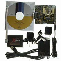
Description
KIT DEV FOR Z8F642 MCU 28PIN
Manufacturer
Zilog
Series
Z8 Encore!®r
Type
MCUr
Datasheets
1.Z8F16800128ZCOG.pdf
(399 pages)
2.Z8F16800128ZCOG.pdf
(3 pages)
3.Z8F16800128ZCOG.pdf
(564 pages)
Specifications of Z8F16800128ZCOG
Contents
Hardware, Software and Documentation
Processor To Be Evaluated
F083A
Data Bus Width
8 bit
Interface Type
RS-232, USB
For Use With/related Products
Z8F642
For Use With
269-4661 - KIT ACC ETHERNET SMART CABLE
Lead Free Status / RoHS Status
Lead free / RoHS Compliant
Other names
269-4677


Table 8. Reset and STOP Mode Recovery Characteristics and Latency
PS025011-1010
Reset Type
System Reset
(non-POR Reset)
System Reset
(POR Reset)
System Reset with
Crystal Oscillator
Enabled
Stop Mode Recovery
Note:
During a System Reset or Stop Mode Recovery, the Internal Precision Oscillator (IPO)
requires 4 s to start up. When the reset type is a System Reset, the Z8 Encore! XP F1680
Series device is held in Reset for 68 IPO cycles. If the crystal oscillator is enabled in Flash
option bits, the Reset period is increased to 568–10068 IPO cycles. For more details, see
EXTLTMG
the Z8 Encore! XP F1680 Series device goes to normal mode immediately after 4 IPO
cycles. The total Stop Mode Recovey delay is less than 6 s. When a Reset occurs due to a
VBO condition, this delay is measured from the time the supply voltage first exceeds the
VBO level (discussed later in this chapter). When a Reset occurs due to a POR condition,
this delay is measured from the time that the supply voltage first exceeds the POR level. If
the external pin reset remains asserted at the end of the Reset period, the device remains in
reset until the pin is deasserted.
After a Stop Mode Recovery, the external crystal oscillator is unstable. Use software to
wait until it is stable before you can use it as main clock.
At the beginning of Reset, all GPIO pins are configured as inputs with pull-up resistor
disabled, except PD0 that is shared with the Reset pin. On Reset, the Port D0 pin is
configured as a bidirectional open-drain Reset. The pin is internally driven Low during
port reset after which the user code may reconfigure this pin as a general-purpose output.
During Reset, the eZ8 CPU and on-chip peripherals are idle; however, the on-chip crystal
oscillator and WDT oscillator continue to function.
On Reset, control registers within the Register File that have a defined Reset value are
loaded with their Reset values. Other control registers (including the Stack Pointer,
Register Pointer, and Flags) and general-purpose RAM are not initialized and undefined
following Reset. The eZ8 CPU fetches the Reset vector at Program Memory addresses
Control Registers
Reset
(as applicable)
Reset
(as applicable)
Reset
(as applicable)
Unaffected, except
RSTSTAT and
OSCCTL registers
description in user option bit. When the reset type is a Stop Mode Recovery,
P R E L I M I N A R Y
Reset Characteristics and Latency
eZ8 CPU
Reset
Reset
Reset
Reset
Reset Latency (Delay)
68 Internal Precision Oscillator Cycles after
IPO starts up
68 Internal Precision Oscillator Cycles +
50 ms Wait time
568–10068 Internal Precision Oscillator
Cycles after IPO starts up, see
description in user option bit for details.
4 Internal Precision Oscillator Cycles after
IPO starts up
Reset, Stop Mode Recovery, and Low-Voltage
Z8 Encore! XP
Product Specification
®
F1680 Series
EXTLTMG
34
Related parts for Z8F16800128ZCOG
Image
Part Number
Description
Manufacturer
Datasheet
Request
R

Part Number:
Description:
Communication Controllers, ZILOG INTELLIGENT PERIPHERAL CONTROLLER (ZIP)
Manufacturer:
Zilog, Inc.
Datasheet:

Part Number:
Description:
KIT DEV FOR Z8 ENCORE 16K TO 64K
Manufacturer:
Zilog
Datasheet:

Part Number:
Description:
KIT DEV Z8 ENCORE XP 28-PIN
Manufacturer:
Zilog
Datasheet:

Part Number:
Description:
DEV KIT FOR Z8 ENCORE 8K/4K
Manufacturer:
Zilog
Datasheet:

Part Number:
Description:
KIT DEV Z8 ENCORE XP 28-PIN
Manufacturer:
Zilog
Datasheet:

Part Number:
Description:
DEV KIT FOR Z8 ENCORE 4K TO 8K
Manufacturer:
Zilog
Datasheet:
Part Number:
Description:
CMOS Z8 microcontroller. ROM 16 Kbytes, RAM 256 bytes, speed 16 MHz, 32 lines I/O, 3.0V to 5.5V
Manufacturer:
Zilog, Inc.
Datasheet:
Part Number:
Description:
Low-cost microcontroller. 512 bytes ROM, 61 bytes RAM, 8 MHz
Manufacturer:
Zilog, Inc.
Datasheet:
Part Number:
Description:
Z8 4K OTP Microcontroller
Manufacturer:
Zilog, Inc.
Datasheet:
Part Number:
Description:
CMOS SUPER8 ROMLESS MCU
Manufacturer:
Zilog, Inc.
Datasheet:
Part Number:
Description:
SL1866 CMOSZ8 OTP Microcontroller
Manufacturer:
Zilog, Inc.
Datasheet:
Part Number:
Description:
SL1866 CMOSZ8 OTP Microcontroller
Manufacturer:
Zilog, Inc.
Datasheet:
Part Number:
Description:
OTP (KB) = 1, RAM = 125, Speed = 12, I/O = 14, 8-bit Timers = 2, Comm Interfaces Other Features = Por, LV Protect, Voltage = 4.5-5.5V
Manufacturer:
Zilog, Inc.
Datasheet:
Part Number:
Description:
Manufacturer:
Zilog, Inc.
Datasheet: