XE8000EV110 Semtech, XE8000EV110 Datasheet - Page 107
XE8000EV110
Manufacturer Part Number
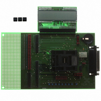
XE8000EV110
Description
EVAL BOARD FOR XE8802AMI035LF
Manufacturer
Semtech
Type
MCUr
Specifications of XE8000EV110
Contents
Fully Assembled Evaluation Board
For Use With/related Products
XE88LC02MI035
Lead Free Status / RoHS Status
Contains lead / RoHS non-compliant


Note that pull-ups are disconnected independent from the value in RegSpiPullup if the corresponding pin is
configured as an output.
16.4 Interrupts map
Irq_spi(0) interrupt is activated at the assertion of the SpiRxFull flag (cf. RegSpiStatus description).
16.5 Function description
Depending on the value of the bit SpiEnable in the RegSpiControl register, the SPI peripheral can work either as
a real SPI interface (master or slave) or as a general purpose 4 bit wide digital input/output port.
16.5.1 SPI interface
16.5.1.1 General operation
The peripheral is configured as an SPI by setting the bit SpiEnable=1 in RegSpiControl. The bit SpiMaster in
RegSpiControl selects the master or slave mode.
The SPI interface supports 4 physical wires between one master device and one or more slave devices (Figure
16-1): MISO (Master In Slave Out), MOSI (Master Out Slave In), SCK (Serial Clock), NSS (Slave Select).
A byte transmission performs a rotate operation between the value stored in the 8 bit shift register of the master
device and the value stored in the 8 bit shift register of the (selected) slave device. The SCK line is used to
synchronize both SPI interfaces.
© Semtech 2006
7-0
7-4
3-0
7-4
3-0
Pos.
Pos.
Pos.
SpiDataIn[7:0]
--
SpiPullup
--
SpiDir[3:0]
RegSpiDataIn
RegSpiPullup
RegSpiDir
interrupt source
Irq_spi(0)
r
r
r/w
r
r/w
Rw
Rw
Rw
00000000
nresetglobal
0000
1
nresetpconf
0000
0
nresetpconf
XE8802 Sensing Machine Data Acquisition MCU
Table 16-9: Interrupts map
Table 16-6: RegSpiDataIn
Table 16-7: RegSpiPullup
Default mapping in the interrupt manager
Table 16-8: RegSpiDir
Reset
Reset
Reset
16-4
SPI mode: reception data byte
I/O mode: input data (only bits 3:0, see Table
16-2, bits 7:4 read 0)
Unused.
Pullup configuration in both SPI and I/O mode
(1=active). Mapping as in Table 16-2.
Unused.
I/O mode only (mapping in Table 16-2)
1: output enabled
0: output disabled
with ZoomingADC™ and LCD driver
irq_bus(21)
Function
Function
Function
www.semtech.com
Related parts for XE8000EV110
Image
Part Number
Description
Manufacturer
Datasheet
Request
R

Part Number:
Description:
EVALUATION BOARD
Manufacturer:
Semtech
Datasheet:
Part Number:
Description:
EVALUATION BOARD
Manufacturer:
Semtech
Datasheet:
Part Number:
Description:
VOLTAGE SUPPRESSOR, TRANSIENT SEMTECH
Manufacturer:
Semtech
Datasheet:

Part Number:
Description:
HIGH VOLTAGE CAPACITORS MONOLITHIC CERAMIC TYPE
Manufacturer:
Semtech Corporation
Datasheet:
Part Number:
Description:
EZ1084CM5.0 AMP POSITIVE VOLTAGE REGULATOR
Manufacturer:
Semtech Corporation
Datasheet:
Part Number:
Description:
3.0 AMP LOW DROPOUT POSITIVE VOLTAGE REGULATORS
Manufacturer:
Semtech Corporation
Datasheet:
Part Number:
Description:
Manufacturer:
Semtech Corporation
Datasheet:
Part Number:
Description:
RailClamp Low Capacitance TVS Diode Array
Manufacturer:
Semtech Corporation
Datasheet:
Part Number:
Description:
Manufacturer:
Semtech Corporation
Datasheet:
Part Number:
Description:
Manufacturer:
Semtech Corporation
Datasheet:
Part Number:
Description:
Manufacturer:
Semtech Corporation
Datasheet:
Part Number:
Description:
Manufacturer:
Semtech Corporation
Datasheet: