XE8000EV110 Semtech, XE8000EV110 Datasheet - Page 116
XE8000EV110
Manufacturer Part Number
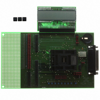
XE8000EV110
Description
EVAL BOARD FOR XE8802AMI035LF
Manufacturer
Semtech
Type
MCUr
Specifications of XE8000EV110
Contents
Fully Assembled Evaluation Board
For Use With/related Products
XE88LC02MI035
Lead Free Status / RoHS Status
Contains lead / RoHS non-compliant


17.4 ZoomingADC™Description
Figure 17-2 gives a more detailed description of the acquisition chain.
17.4.1
Figure 17-1 shows the general block diagram of the acquisition chain (AC). A control block (not shown in Figure
17-1) manages all communications with the CoolRisc™ microcontroller.
differential channels.
The core of the zooming section is made of three differential programmable amplifiers (PGA). After selection of a
combination of input and reference signals V
stages 1 to 3. Fine gain programming up to 1'000V/V is possible. In addition, the last two stages provide
programmable offset. Each amplifier can be bypassed if needed.
The output of the PGA stages is directly fed to the analog-to-digital converter (ADC), which converts the signal
V
Like most ADCs intended for instrumentation or sensing applications, the ZoomingADC™ is an over-sampled
converter (See Note
positive and negative input voltages). In first approximation, the ADC output result relative to full-scale (FS) delivers
the quantity:
in two's complement (see Sections 17.4 and 17.7 for details). The output code OUT
≅ -V
relationship:
where GD
1 Note: Over-sampled converters are operated with a sampling frequency f
1'000 times the input signal bandwidth). The sampling frequency to throughput ratio is large (typically 10-500). These converters include digital
decimation filtering. They are mainly used for high resolution, and/or low-to-medium speed applications.
© Semtech 2006
Analog inputs can be selected among eight input channels, while reference input is selected between two
IN,ADC
REF
into digital.
/2 to +V
pos.
pos.
V
6:0
5:1
OUT
7
7
6
0
IN
FS
TOT
Acquisition Chain
,
ADC
2 /
ADC
is the total PGA gain, and GDoff
RegAcCfg4
RegAcCfg5
=
PGA3_OFFSET[6:0]
REF
≅
GD
/2 respectively. As will be shown in section 17.6, V
V
V
AMUX[4:0]
1
REF
TOT
IN
reserved
). The ADC is a so-called incremental converter, with bipolar operation (the ADC accepts both
VMUX
BUSY
,
ADC
DEF
⋅
2 /
V
IN
−
GDoff
TOT
rw
r
r w
rw
r
w r0
r w
r w
⋅
V
REF
XE8802 Sensing Machine Data Acquisition MCU
reset
0
0000000
nresetglobal
reset
0 nresetglobal
0
00000
nresetglobal
0 nresetglobal
(V)
TOT
IN
Table 17-8: RegAcCfg4
Table 17-9: RegAcCfg5
and V
is the total PGA offset.
17-4
REF
, the input voltage is modulated and amplified through
S
with ZoomingADC™ and LCD driver
description
description
much higher than the input signal's Nyquist rate (typically f
Input channel configuration selector
IN,ADC
Selects default configuration
(Eq. 1)
(Eq. 2)
PGA3 stage offset selection
Reference channel selector
is related to input voltage V
Activity flag
Unused
ADC
is -FS/2 to +FS/2 for V
www.semtech.com
IN
by the
S
IN,ADC
is 20-
Related parts for XE8000EV110
Image
Part Number
Description
Manufacturer
Datasheet
Request
R

Part Number:
Description:
EVALUATION BOARD
Manufacturer:
Semtech
Datasheet:
Part Number:
Description:
EVALUATION BOARD
Manufacturer:
Semtech
Datasheet:
Part Number:
Description:
VOLTAGE SUPPRESSOR, TRANSIENT SEMTECH
Manufacturer:
Semtech
Datasheet:

Part Number:
Description:
HIGH VOLTAGE CAPACITORS MONOLITHIC CERAMIC TYPE
Manufacturer:
Semtech Corporation
Datasheet:
Part Number:
Description:
EZ1084CM5.0 AMP POSITIVE VOLTAGE REGULATOR
Manufacturer:
Semtech Corporation
Datasheet:
Part Number:
Description:
3.0 AMP LOW DROPOUT POSITIVE VOLTAGE REGULATORS
Manufacturer:
Semtech Corporation
Datasheet:
Part Number:
Description:
Manufacturer:
Semtech Corporation
Datasheet:
Part Number:
Description:
RailClamp Low Capacitance TVS Diode Array
Manufacturer:
Semtech Corporation
Datasheet:
Part Number:
Description:
Manufacturer:
Semtech Corporation
Datasheet:
Part Number:
Description:
Manufacturer:
Semtech Corporation
Datasheet:
Part Number:
Description:
Manufacturer:
Semtech Corporation
Datasheet:
Part Number:
Description:
Manufacturer:
Semtech Corporation
Datasheet: