STR710-EVAL STMicroelectronics, STR710-EVAL Datasheet
STR710-EVAL
Specifications of STR710-EVAL


Related parts for STR710-EVAL


STR710-EVAL Summary of contents
Page 1
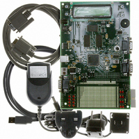
... Kbytes embedded flash with “best-in-class” random access time, 64 Kbytes on-chip high speed SRAM and serial communication interfaces, including USB and CAN. The STR710-EVAL board includes SRAM and flash memory on the EMI to enable full freedom in development of large programs before custom hardware is designed. It integrates LCD, ...
Page 2
... External analog . . . . . . . . . . . . . . . . . . . . . . . . . . . . . . . . . . . . . . . . . . . . . . . . 7 2.12 Analog input . . . . . . . . . . . . . . . . . . . . . . . . . . . . . . . . . . . . . . . . . . . . . . . . . . 7 2.13 LEDs . . . . . . . . . . . . . . . . . . . . . . . . . . . . . . . . . . . . . . . . . . . . . . . . . . . . . . . . 8 2.14 Option jumper placement . . . . . . . . . . . . . . . . . . . . . . . . . . . . . . . . . . . . . . . . 9 2.15 Option switch settings . . . . . . . . . . . . . . . . . . . . . . . . . . . . . . . . . . . . . . . . . . 10 3 Connectors . . . . . . . . . . . . . . . . . . . . . . . . . . . . . . . . . . . . . . . . . . . . . . . . . . 13 3.1 USB . . . . . . . . . . . . . . . . . . . . . . . . . . . . . . . . . . . . . . . . . . . . . . . . . . . . . . . 13 3.2 CAN bus connector . . . . . . . . . . . . . . . . . . . . . . . . . . . . . . . . . . . . . . . . . . . . 13 3.3 External analog . . . . . . . . . . . . . . . . . . . . . . . . . . . . . . . . . . . . . . . . . . . . . . . 13 3.4 RS232 serial data connector . . . . . . . . . . . . . . . . . . . . . . . . . . . . . . . . . . . . . 14 3.5 Debug . . . . . . . . . . . . . . . . . . . . . . . . . . . . . . . . . . . . . . . . . . . . . . . . . . . . . 14 4 Schematics . . . . . . . . . . . . . . . . . . . . . . . . . . . . . . . . . . . . . . . . . . . . . . . . . . 15 5 Revision history . . . . . . . . . . . . . . . . . . . . . . . . . . . . . . . . . . . . . . . . . . . . . . 25 1/27 STR710-EVAL ...
Page 3
... Because the STR710FZ2T6 is the superset of the STR71xF series, with 144-pin, EMI, 256 Kbytes of flash and 64 Kbytes of SRAM, an alternative use of the STR710-EVAL board evaluation platform for STR711F and STR712F devices. The hardware platform of the STR710F series is supported by an extensive software support package, including device drivers in ANSI C source form and demonstration software ...
Page 4
... LD20, ● low consumption LEDs red: LD3, LD4, LD5, LD6, LD8,LD9, LD10, LD11, LD12, LD13, LD14, LD15, LD16, LD17, LD18, LD19. 2 Note: The LCD I C0 connection may be used, although the I 3/ connector is not fitted. STR710-EVAL 2 C0 interface: IC9. Section 4: Schematics Section 4: ...
Page 5
... STR710-EVAL 2 Hardware Figure 1. STR710-EVAL board layout block diagram JTAG CN9 RS232-A UART 0 Rx and Tx only CN7 External analog CN6 Variable resistor R63 RS232-B UART Switch selectable Rx and Tx only CN8 LD20 Buzzer WAKEUP push button LD21 WAKE Board reset push button RST ...
Page 6
... Hardware Figure 2. STR710-EVAL board system block diagram In-circuit emulator RS232 Rx and Tx RS232 Rx and Tx switchable Variable resistor Piezzo Buzzer 5 V power 5/27 Prototype area JTAG UART0 UART EMI Analog Audio out STR710-EVAL LEDs CAN USB Flash SRAM LCD EEPROM SPI serial flash ...
Page 7
... STR710-EVAL 2.1 Overview The STR710-EVAL board is a general purpose evaluation platform with USB, CAN (controller area network) and RS232 interfaces. 2.2 Processor The board supports the STR710FZ2T6 ARM7TDMI runs at a frequency of 48 MHz. Boot modes and configuration options are set using microswitches. ...
Page 8
... External analog An external analog input connector is provided, see and Figure 11: STR710-EVAL board top level page page 15 2.12 Analog input The analog input to ADC is demonstrated by the variable resistor R63. Although there is a thermistor connected up to the analogue input AIN.1 in the schematics EVAL board top level page page 15 the product ...
Page 9
... STR710-EVAL 2.13 LEDs Software controlled LEDs The LEDs in Table 2 page 15 . Table 2. Software controlled LEDs LED LD20 LD3 LD4 LD5 LD6 LD8 LD9 LD10 LD11 LD12 LD13 LD14 LD15 LD16 LD17 LD18 LD19 Status LEDs Table 3. Status LEDs LED LD1 +5 V LD2 +3 ...
Page 10
... Hardware 2.14 Option jumper placement Figure 3. Option jumpers, resistors and switches SW10 J4 J3 SW9 SW11 WAKE SW12 RST 9/27 SW15 SW13 SW14 SW8 Prototype area STR710FZ2T6 TM ARM7TDMI STR710-EVAL SW7 NXT SEL SW5 J1 SW1 SW2 J5 SW6 SW3 SW4 ...
Page 11
... STR710-EVAL Table 4. Option jumpers Jumper Figure Figure 16 on page Figure 12 on page 16 J4 Figure 19 on page 23 Figure 12 on page 16 J5 Jumpers are fitted as shown in Figure 4. Jumper positions 2.15 Option switch settings Table 5. Option switch settings Switch SW1 Figure 16 on page 20 SW2 ...
Page 12
... Clock FROZEN RAM RAM mapped System executes at 0h code from internal RAM For Lab development EXTMEM EXTMEM System executes mapped at oh code from external memory STR710-EVAL Description Table 6 on page 11 . Table 6 on page 11 . Table 6 on page 11 . Notes SW14 BOOT0 SW13 BOOT1 SW15 ...
Page 13
... STR710-EVAL Figure 5. Switch positions 1-2 Microswitches 2-3 2 Hardware Slide switches 12/27 ...
Page 14
... Analog input 13/27 USB-B Pin Description Pin CAN - data Pin Description 4 Not connected Not connected 6 GROUND External analog 1 2 Pin 2 STR710-EVAL Description Pin Description DP 4 GND 5 Pin Description 7 CAN H, high side bus output 8 Pull down to GROUND 9 Pull up to +3V3 V Description Ground ...
Page 15
... STR710-EVAL 3.4 RS232 serial data connector 9-pin general purpose D-type male connectors Figure 9. RS232 transmit and receive connectors: CN7, CN8 RS232 - Data Table 10. RS232 connector pinout: CN7, CN8 Pin Description 1 Shorted to pin 4 and 6 2 R1IN (port A), R2IN (port B) 3 T1OUT (port A), T2OUT (port ...
Page 16
... Schematics 4 Schematics Figure 11. STR710-EVAL board top level page 15/27 STR710-EVAL ...
Page 17
... STR710-EVAL Figure 12. STR710-EVAL board top-level page Schematics 16/27 ...
Page 18
... Schematics Figure 13. EMI flash 17/27 STR710-EVAL ...
Page 19
... STR710-EVAL Figure 14. EMI SRAM 4 Schematics 18/27 ...
Page 20
... Schematics Figure 15. USB Interface 19/27 STR710-EVAL ...
Page 21
... STR710-EVAL Figure 16. CAN interface 4 Schematics 20/27 ...
Page 22
... Schematics Figure 17. Serial ROM interface 21/27 STR710-EVAL ...
Page 23
... STR710-EVAL Figure 18. RS232 interface 4 Schematics 22/27 ...
Page 24
... Schematics Figure 19. ARM JTAG interface 23/27 STR710-EVAL ...
Page 25
... STR710-EVAL Figure 20. LCD interface 4 Schematics 24/27 ...
Page 26
... R83. Updated Section 2.9: CAN interface on page 7 Chapter 4: Schematics Updated schematics. Removed list of third party support vendors from description. STR710-EVAL Changes to list the JTAG connector CN9. to improve the USB interface to improve the CAN interface to show J5 is not fitted. Table 5 on page 10 ...
Page 27
... No license is granted by implication or otherwise under any patent or patent rights of STMicroelectronics. Specifications mentioned in this publication are subject to change without notice. This publication supersedes and replaces all information previously supplied. STMicroelectronics products are not authorized for use as critical components in life support devices or systems without express written approval of STMicroelectronics ...