STR710-EVAL STMicroelectronics, STR710-EVAL Datasheet - Page 4
STR710-EVAL
Manufacturer Part Number
STR710-EVAL
Description
BOARD EVAL FOR STR71X SER MCU
Manufacturer
STMicroelectronics
Type
MCUr
Specifications of STR710-EVAL
Contents
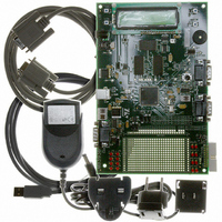
STR710 Evaluation Board, LCD, I2C EEPROM, 4MBytes EMI Flash and 4MBytes EMI SRAM
Processor To Be Evaluated
STR710FZ2T6
Data Bus Width
32 bit
Interface Type
RS-232, USB
Silicon Manufacturer
ST Micro
Core Architecture
ARM
Core Sub-architecture
ARM7TDMI
Silicon Core Number
STR7
Silicon Family Name
STR71x
Kit Contents
Evaluation Board For STR71xF
Rohs Compliant
NA
For Use With/related Products
STR71x ARM7 Series
Lead Free Status / RoHS Status
Contains lead / RoHS non-compliant
Other names
497-4516


1 Introduction
1.2
1.3
1.4
Note:
3/27
●
Board interface connections
Diagrams and wiring descriptions for these connectors are provided in
on page 15
●
●
●
●
●
●
●
●
●
●
●
Push buttons
The following push buttons are provided:
●
●
●
●
Displays
The following LCD and LEDs are provided:
●
●
●
●
●
●
The LCD I
–
Serial ROMs:
–
–
USB, support USB device using a type B connector: CN3,
CAN uses a single 9 D-type connector with microswitch selectable low or high speed
transceiver: CN1,
UART0 (Rx and Tx only) connected to a 9-way male D-type RS232 connector: CN7,
UART1 and 2 (Rx and Tx only) switch selectable, connected to a 9-way male D-type
RS232 connector: CN8 ,
JTAG, 20 pin IDC connector: CN9,
Piezo buzzer: SPKR1,
variable resistor, voltage range 0 to 2.5 V: R63,
prototype area: GD1,
test points, various test points are located throughout the board, for details see
Schematics on page 15
external analog: CN6,
main power supply: CN2.
reset, board reset: SW12,
wakeup, push button to bring processor out of low power mode: SW11,
select, programmable switch: SW4,
next, programmable switch: SW3.
LCD display, 2x16 LCD display connected to a parallel EMI LCD interface; green back light
display: LCD1,
surface mount red, +5 V and +3.3 V power indicators: LD1, LD2,
surface mount orange, USB powered: LD7,
surface mount orange indicates standby status: LD21,
bi-color red/green: LD20,
low consumption LEDs red: LD3, LD4, LD5, LD6, LD8,LD9, LD10, LD11, LD12, LD13,
LD14, LD15, LD16, LD17, LD18, LD19.
RTC real-time clock for wakeup from standby mode with embedded 32 KHz oscillator.
1-Mbit SPI serial flash connected to the buffered serial peripheral interface (BSPI):
IC11,
I
2
2
C EEPROM: 8-kbit EEPROM connected to the I
. The following connections are supported by the board:
C0 connection may be used, although the I
,
2
C0 connector is not fitted.
2
C0 interface: IC9.
Section 4: Schematics
STR710-EVAL
Section 4:
Related parts for STR710-EVAL
Image
Part Number
Description
Manufacturer
Datasheet
Request
R

Part Number:
Description:
KIT STARTER HITEX FULL STR7/9
Manufacturer:
STMicroelectronics
Datasheet:

Part Number:
Description:
IC MCU ARM7 TDMI 256K 144TQFP
Manufacturer:
STMicroelectronics
Datasheet:

Part Number:
Description:
MCU 32BIT 256KB FLASH 100-LQFP
Manufacturer:
STMicroelectronics
Datasheet:

Part Number:
Description:
IC MCU ARM7 TDMI 256K 64-LQFP
Manufacturer:
STMicroelectronics
Datasheet:
Part Number:
Description:
MCU 32BIT 64KB FLASH 64-LQFP
Manufacturer:
STMicroelectronics
Datasheet:
Part Number:
Description:
IC MCU ARM7 TDMI 128K 64-LQFP
Manufacturer:
STMicroelectronics
Datasheet:

Part Number:
Description:
MCU ARM7 32BIT 64-LFBGA
Manufacturer:
STMicroelectronics
Datasheet:

Part Number:
Description:
MCU 32BIT 128K FLASH 100-TQFP
Manufacturer:
STMicroelectronics
Datasheet:
Part Number:
Description:
IC MCU ARM7 128K FLASH 100-TQFP
Manufacturer:
STMicroelectronics
Datasheet:
Part Number:
Description:
MCU 32BIT 128KB FLASH 100-LQFP
Manufacturer:
STMicroelectronics
Datasheet:
Part Number:
Description:
MCU 32BIT 256KB FLASH 100-TQFP
Manufacturer:
STMicroelectronics
Datasheet:
Part Number:
Description:
IC MCU ARM7 TDMI 256K 64-LQFP
Manufacturer:
STMicroelectronics
Datasheet:

Part Number:
Description:
MCU 32BIT 256KB FLASH 144-LQFP
Manufacturer:
STMicroelectronics
Datasheet:

Part Number:
Description:
MCU 32BIT 256KB FLASH 144-LFBGA
Manufacturer:
STMicroelectronics
Datasheet:
Part Number:
Description:
IC MCU ARM7 256K FLASH 100-TQFP
Manufacturer:
STMicroelectronics
Datasheet: