C8051F064EK Silicon Laboratories Inc, C8051F064EK Datasheet - Page 119
C8051F064EK
Manufacturer Part Number
C8051F064EK
Description
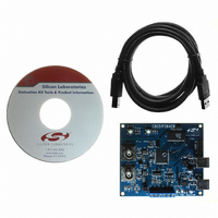
KIT EVAL FOR C8051F064
Manufacturer
Silicon Laboratories Inc
Type
MCUr
Specifications of C8051F064EK
Contents
Evaluation Board, Power Supply, USB Cables, Adapter and Documentation
Processor To Be Evaluated
C8051F06x
Interface Type
USB
Silicon Manufacturer
Silicon Labs
Core Architecture
8051
Silicon Core Number
C8051F064
Silicon Family Name
C8051F06x
Lead Free Status / RoHS Status
Contains lead / RoHS non-compliant
For Use With/related Products
C8051F064
Lead Free Status / Rohs Status
Lead free / RoHS Compliant
Other names
336-1219


Comparator interrupts can be generated on either rising-edge and falling-edge output transitions. (For
Interrupt enable and priority control, see
falling -edge interrupts are enabled using the comparator’s Rising/Falling Edge Interrupt Enable Bits (CPn-
RIE and CPnFIE) in their respective Comparator Mode Selection Register (CPTnMD), shown in
Figure 12.4. These bits allow the user to control which edge (or both) will cause a comparator interrupt.
However, the comparator interrupt must also be enabled in the Extended Interrupt Enable Register (EIE1).
The CPnFIF flag is set to logic 1 upon a Comparator falling-edge interrupt, and the CPnRIF flag is set to
logic 1 upon the Comparator rising-edge interrupt. Once set, these bits remain set until cleared by soft-
ware. The output state of a Comparator can be obtained at any time by reading the CPnOUT bit. A Com-
parator is enabled by setting its respective CPnEN bit to logic 1, and is disabled by clearing this bit to logic
0.Upon enabling a comparator, the output of the comparator is not immediately valid. Before using a com-
parator as an interrupt or reset source, software should wait for a minimum of the specified “Power-up
time” as specified in Table 12.1, “Comparator Electrical Characteristics,” on page 122.
12.1. Comparator Inputs
The Port pins selected as comparator inputs should be configured as analog inputs in the Port 2 Input Con-
figuration Register (for details on Port configuration, see
Inputs” on page
207). The inputs for Comparator are on Port 2 as follows:
Comparator Input
CP0 +
CP1 +
CP2 +
CP0 -
CP1 -
CP2 -
Section “13.3. Interrupt Handler” on page
Rev. 1.2
C8051F060/1/2/3/4/5/6/7
Section “18.1.3. Configuring Port Pins as Digital
Port PIN
P2.6
P2.7
P2.2
P2.3
P2.4
P2.5
151). The rising and/or
119
Related parts for C8051F064EK
Image
Part Number
Description
Manufacturer
Datasheet
Request
R

Part Number:
Description:
SMD/C°/SINGLE-ENDED OUTPUT SILICON OSCILLATOR
Manufacturer:
Silicon Laboratories Inc
Part Number:
Description:
Manufacturer:
Silicon Laboratories Inc
Datasheet:
Part Number:
Description:
N/A N/A/SI4010 AES KEYFOB DEMO WITH LCD RX
Manufacturer:
Silicon Laboratories Inc
Datasheet:
Part Number:
Description:
N/A N/A/SI4010 SIMPLIFIED KEY FOB DEMO WITH LED RX
Manufacturer:
Silicon Laboratories Inc
Datasheet:
Part Number:
Description:
N/A/-40 TO 85 OC/EZLINK MODULE; F930/4432 HIGH BAND (REV E/B1)
Manufacturer:
Silicon Laboratories Inc
Part Number:
Description:
EZLink Module; F930/4432 Low Band (rev e/B1)
Manufacturer:
Silicon Laboratories Inc
Part Number:
Description:
I°/4460 10 DBM RADIO TEST CARD 434 MHZ
Manufacturer:
Silicon Laboratories Inc
Part Number:
Description:
I°/4461 14 DBM RADIO TEST CARD 868 MHZ
Manufacturer:
Silicon Laboratories Inc
Part Number:
Description:
I°/4463 20 DBM RFSWITCH RADIO TEST CARD 460 MHZ
Manufacturer:
Silicon Laboratories Inc
Part Number:
Description:
I°/4463 20 DBM RADIO TEST CARD 868 MHZ
Manufacturer:
Silicon Laboratories Inc
Part Number:
Description:
I°/4463 27 DBM RADIO TEST CARD 868 MHZ
Manufacturer:
Silicon Laboratories Inc
Part Number:
Description:
I°/4463 SKYWORKS 30 DBM RADIO TEST CARD 915 MHZ
Manufacturer:
Silicon Laboratories Inc
Part Number:
Description:
N/A N/A/-40 TO 85 OC/4463 RFMD 30 DBM RADIO TEST CARD 915 MHZ
Manufacturer:
Silicon Laboratories Inc
Part Number:
Description:
I°/4463 20 DBM RADIO TEST CARD 169 MHZ
Manufacturer:
Silicon Laboratories Inc