MPC8313E-RDBB Freescale Semiconductor, MPC8313E-RDBB Datasheet - Page 37
MPC8313E-RDBB
Manufacturer Part Number
MPC8313E-RDBB
Description
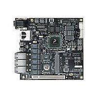
BOARD CPU 8313E VER 2.1
Manufacturer
Freescale Semiconductor
Series
PowerQUICC II™ PROr
Type
MPUr
Datasheets
1.MPC8313CZQAFFB.pdf
(100 pages)
2.MPC8313E-RDBB.pdf
(52 pages)
3.MPC8313E-RDBB.pdf
(2 pages)
Specifications of MPC8313E-RDBB
Contents
Board
Processor To Be Evaluated
MPC8xxx
Data Bus Width
32 bit
Interface Type
Ethernet, USB, JTAG, SPI, UART
Dimensions
170 mm x 170 mm
Operating Supply Voltage
3.3 V
For Use With/related Products
MPC8313E
Lead Free Status / RoHS Status
Lead free / RoHS Compliant


To illustrate these definitions using real values, consider the case of a CML (current mode logic)
transmitter that has a common mode voltage of 2.25 V and each of its outputs, TD and TD, has a swing
that goes between 2.5 and 2.0 V. Using these values, the peak-to-peak voltage swing of each signal (TD or
TD) is 500 mV p-p, which is referred as the single-ended swing for each signal. In this example, since the
differential signaling environment is fully symmetrical, the transmitter output’s differential swing (V
has the same amplitude as each signal’s single-ended swing. The differential output signal ranges between
500 and –500 mV, in other words, V
differential voltage (V
Freescale Semiconductor
4. Differential peak voltage, V
5. Differential peak-to-peak, V
6. Differential waveform
7. Common mode voltage, V
The peak value of the differential transmitter output signal or the differential receiver input signal
is defined as differential peak voltage, V
Since the differential output signal of the transmitter and the differential input signal of the receiver
each range from A – B to –(A – B) volts, the peak-to-peak value of the differential transmitter
output signal or the differential receiver input signal is defined as differential peak-to-peak voltage,
V
twice of the differential peak. For example, the output differential peak-peak voltage can also be
calculated as V
The differential waveform is constructed by subtracting the inverting signal (TXn, for example)
from the non-inverting signal (TXn, for example) within a differential pair. There is only one signal
trace curve in a differential waveform. The voltage represented in the differential waveform is not
referenced to ground. Refer to
The common mode voltage is equal to one half of the sum of the voltages between each conductor
of a balanced interchange circuit and ground. In this example, for SerDes output, V
(V
voltages within a differential pair. In a system, the common mode voltage may often differ from
one component’s output to the other’s input. Sometimes, it may be even different between the
receiver input and driver output circuits within the same component. It’s also referred as the DC
offset in some occasion.
A Volts
B Volts
DIFFp-p
TXn
+ V
= 2 × V
TXn
Figure 22. Differential Voltage Definitions for Transmitter or Receiver
MPC8313E PowerQUICC
TX n or RX n
TX n or RX n
)/2 = (A + B)/2, which is the arithmetic mean of the two complimentary output
DIFFp
TX-DIFFp-p
DIFFp
) is 500 mV. The peak-to-peak differential voltage (V
= 2 × |(A – B)| volts, which is twice of differential swing in amplitude, or
Differential Peak-Peak Voltage, V
= 2 × |V
cm
DIFFp
OD
DIFFp-p
Figure 22
is 500 mV in one phase and –500 mV in the other phase. The peak
™
Differential Swing, V
Differential Peak Voltage, V
OD
II Pro Processor Hardware Specifications, Rev. 3
|.
DIFFp
as an example for differential waveform.
= |A – B| volts.
ID
DIFFpp
or V
OD
DIFFp
= 2*V
= A – B
= |A – B|
DIFFp
(not shown)
High-Speed Serial Interfaces (HSSI)
DIFFp-p
V
cm
) is 1000 mV p-p.
= (A + B)/2
cm_out
=
OD
37
)
Related parts for MPC8313E-RDBB
Image
Part Number
Description
Manufacturer
Datasheet
Request
R

Part Number:
Description:
Mpc8313e Powerquicc Ii Pro Processor
Manufacturer:
Freescale Semiconductor, Inc
Datasheet:

Part Number:
Description:
BOARD PROCESSOR
Manufacturer:
Freescale Semiconductor
Datasheet:

Part Number:
Description:
BOARD CPU 8313E VER 2.2
Manufacturer:
Freescale Semiconductor
Datasheet:
Part Number:
Description:
Microprocessors - MPU 8313 REV2.2 PB ENC EXT
Manufacturer:
Freescale Semiconductor
Datasheet:
Part Number:
Description:
Microprocessors - MPU 8313 REV2.2 PB W/ENC
Manufacturer:
Freescale Semiconductor
Datasheet:
Part Number:
Description:
Microprocessors - MPU 8313 REV2.2 PB NO EN EXT
Manufacturer:
Freescale Semiconductor
Datasheet:
Part Number:
Description:
Microprocessors - MPU 8313 REV2.2 PB NO ENC
Manufacturer:
Freescale Semiconductor
Datasheet:
Part Number:
Description:
Manufacturer:
Freescale Semiconductor, Inc
Datasheet:
Part Number:
Description:
Manufacturer:
Freescale Semiconductor, Inc
Datasheet:
Part Number:
Description:
Manufacturer:
Freescale Semiconductor, Inc
Datasheet:
Part Number:
Description:
Manufacturer:
Freescale Semiconductor, Inc
Datasheet:
Part Number:
Description:
Manufacturer:
Freescale Semiconductor, Inc
Datasheet:
Part Number:
Description:
Manufacturer:
Freescale Semiconductor, Inc
Datasheet:
Part Number:
Description:
Manufacturer:
Freescale Semiconductor, Inc
Datasheet:
Part Number:
Description:
Manufacturer:
Freescale Semiconductor, Inc
Datasheet: