SDK-XAM3517-10-256512R Logic, SDK-XAM3517-10-256512R Datasheet - Page 12
SDK-XAM3517-10-256512R
Manufacturer Part Number
SDK-XAM3517-10-256512R
Description
KIT DEV ZOOM EXPERIMENTER AM3517
Manufacturer
Logic
Series
Zoom™r
Type
Single Board Computers (SBC)r
Specifications of SDK-XAM3517-10-256512R
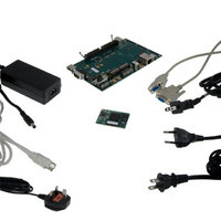
Contents
Board, Adapter, Cables, Documentation, Power Supply, Software
For Use With/related Products
AM3517
Lead Free Status / RoHS Status
Lead free / RoHS Compliant
Other names
460-3486
SDK-XAM3517-10-256512R
SDK-XAM3517-10-256512R


10
ZOOM AM3517
eXperimenter Kit
QuickStart Guide
2.3 Connect Development Kit to PC
In order to communicate with the AM3517 SOM-M2, the development kit needs to be
connected to a PC. The following steps will walk you through this process for communicating
with the AM3517 processor.
Figure 2.3 – Connect Null-Modem Serial Cable to eXperimenter Baseboard
3.
1.
2.
Visually verify that the BTB socket connectors on the SOM-M2 and eXperimenter
baseboard have mated correctly. To remove the SOM-M2, pull up on the board
above the BTB socket connectors. Attempt to pull straight up and refrain from
flexing the printed circuit board (PCB) to avoid damaging the SOM-M2.
Connect the null-modem serial cable (supplied in the kit) to the serial port
connector on the eXperimenter baseboard and to an empty COM port on the your
PC. See Figure 2.3.
Note: If your computer does not have a serial COM port, you can use the USB
Type B serial debug port on the baseboard and a USB A to B cable (not included).
More detailed information on this setup option is available in the Zoom AM3517
Development Kit User Manual, available on the Logic website:
http://support.logicpd.com/downloads/1251/.
Connect the regulated 5V power supply to the appropriate power adapter for the
geographic region in which you are using the development kit.
Related parts for SDK-XAM3517-10-256512R
Image
Part Number
Description
Manufacturer
Datasheet
Request
R

Part Number:
Description:
IC ARITHMETIC LOGIC 4BIT 24-DIP
Manufacturer:
Fairchild Semiconductor
Datasheet:

Part Number:
Description:
IC ARITHMETIC LOGIC 4BIT 20-DIP
Manufacturer:
Fairchild Semiconductor
Datasheet:
Part Number:
Description:
IC ARITHMETIC LOGIC 4BIT 20-DIP
Manufacturer:
Fairchild Semiconductor
Datasheet:

Part Number:
Description:
IC ARITHMETIC LOGIC 4BIT 24-DIP
Manufacturer:
Fairchild Semiconductor
Datasheet:

Part Number:
Description:
IC TRANSL LOGIC 16-TQFN
Manufacturer:
Maxim Integrated Products
Datasheet:

Part Number:
Description:
Logic Output Optocouplers 8-Pin Optocoupler Logic aC Line
Manufacturer:
Fairchild Semiconductor
Datasheet:

Part Number:
Description:
Logic Output Optocouplers 20mA Current Loop
Manufacturer:
Avago Technologies US Inc.
Datasheet:
Part Number:
Description:
Logic Output Optocouplers DIP-8 LOG OUT/AC IN
Manufacturer:
Fairchild Semiconductor
Datasheet:

Part Number:
Description:
OPTOCOUPLER, LOGIC GATE, 5000VRMS
Manufacturer:
Avago Technologies US Inc.
Datasheet:

Part Number:
Description:
OPTOCOUPLER, LOGIC GATE, 2500VRMS
Manufacturer:
Fairchild Semiconductor
Datasheet:
Part Number:
Description:
OPTOCOUPLER, LOGIC GATE, 2500VRMS
Manufacturer:
Fairchild Semiconductor
Datasheet:
Part Number:
Description:
OPTOCOUPLER, LOGIC GATE, 2500VRMS
Manufacturer:
Fairchild Semiconductor
Datasheet:

Part Number:
Description:
OPTOCOUPLER, LOGIC GATE, 2500VRMS
Manufacturer:
Fairchild Semiconductor
Datasheet:
Part Number:
Description:
OPTOCOUPLER, LOGIC GATE, 3750VRMS
Manufacturer:
Fairchild Semiconductor
Part Number:
Description:
OPTOCOUPLER, LOGIC GATE, 3750VRMS
Manufacturer:
Fairchild Semiconductor