TOOLSTICK560DC Silicon Laboratories Inc, TOOLSTICK560DC Datasheet - Page 134
TOOLSTICK560DC
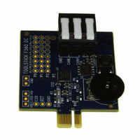
Manufacturer Part Number
TOOLSTICK560DC
Description
DAUGHTER CARD TOOLSTICK F560
Manufacturer
Silicon Laboratories Inc
Series
ToolStickr
Type
MCUr
Specifications of TOOLSTICK560DC
Contents
Daughter Card
Processor To Be Evaluated
C8051F55x, C8051F56x, C8051F57x
Interface Type
USB
Operating Supply Voltage
2.7 V to 3.6 V
Lead Free Status / RoHS Status
Lead free / RoHS Compliant
For Use With/related Products
C8051F55x, C8051F56x, C8051F57x
For Use With
336-1345 - TOOLSTICK BASE ADAPTER336-1182 - ADAPTER USB DEBUG FOR C8051FXXX
Lead Free Status / Rohs Status
Lead free / RoHS Compliant
Other names
336-1719


C8051F55x/56x/57x
15.2. Stop Mode
Setting the Stop Mode Select bit (PCON.1) causes the controller core to enter Stop mode as soon as the
instruction that sets the bit completes execution. In Stop mode the internal oscillator, CPU, and all digital
peripherals are stopped; the state of the external oscillator circuit is not affected. Each analog peripheral
(including the external oscillator circuit) may be shut down individually prior to entering Stop Mode. Stop
mode can only be terminated by an internal or external reset. On reset, the device performs the normal
reset sequence and begins program execution at address 0x0000.
If enabled, the Missing Clock Detector will cause an internal reset and thereby terminate the Stop mode.
The Missing Clock Detector should be disabled if the CPU is to be put to in STOP mode for longer than the
MCD timeout of 100 µs.
15.3. Suspend Mode
Setting the SUSPEND bit (OSCICN.5) causes the hardware to halt the CPU and the high-frequency inter-
nal oscillator, and go into Suspend mode as soon as the instruction that sets the bit completes execution.
All internal registers and memory maintain their original data. Most digital peripherals are not active in Sus-
pend mode. The exception to this is the Port Match feature.
Suspend mode can be terminated by three types of events, a port match (described in Section “19.5. Port
Match” on page 177), a Comparator low output (if enabled), or a device reset event. When Suspend mode
is terminated, the device will continue execution on the instruction following the one that set the SUSPEND
bit. If the wake event was configured to generate an interrupt, the interrupt will be serviced upon waking
the device. If Suspend mode is terminated by an internal or external reset, the CIP-51 performs a normal
reset sequence and begins program execution at address 0x0000.
Note: When entering suspend mode, firmware must set the ZTCEN bit in REF0CN (SFR Definition 7.1).
134
Rev. 1.1
Related parts for TOOLSTICK560DC
Image
Part Number
Description
Manufacturer
Datasheet
Request
R

Part Number:
Description:
KIT TOOL EVAL SYS IN A USB STICK
Manufacturer:
Silicon Laboratories Inc
Datasheet:

Part Number:
Description:
TOOLSTICK DEBUG ADAPTER
Manufacturer:
Silicon Laboratories Inc
Datasheet:

Part Number:
Description:
TOOLSTICK BASE ADAPTER
Manufacturer:
Silicon Laboratories Inc
Datasheet:

Part Number:
Description:
TOOLSTICK DAUGHTER CARD
Manufacturer:
Silicon Laboratories Inc
Datasheet:

Part Number:
Description:
TOOLSTICK DAUGHTER CARD
Manufacturer:
Silicon Laboratories Inc
Datasheet:

Part Number:
Description:
TOOLSTICK DAUGHTER CARD
Manufacturer:
Silicon Laboratories Inc
Datasheet:

Part Number:
Description:
TOOLSTICK PROGRAMMING ADAPTER
Manufacturer:
Silicon Laboratories Inc
Datasheet:

Part Number:
Description:
TOOLSTICK DAUGHTER CARD
Manufacturer:
Silicon Laboratories Inc
Datasheet:

Part Number:
Description:
KIT STARTER TOOLSTICK
Manufacturer:
Silicon Laboratories Inc
Datasheet:

Part Number:
Description:
KIT UNIVERSITY TOOLSTICK STARTER
Manufacturer:
Silicon Laboratories Inc
Datasheet:

Part Number:
Description:
DAUGHTER CARD TOOLSTICK F330
Manufacturer:
Silicon Laboratories Inc
Datasheet:

Part Number:
Description:
CARD DAUGHTER UNIVRSTY TOOLSTICK
Manufacturer:
Silicon Laboratories Inc
Datasheet:

Part Number:
Description:
DAUGHTER CARD TOOLSTICK F582
Manufacturer:
Silicon Laboratories Inc
Datasheet:

Part Number:
Description:
DAUGHTER CARD TOOLSTICK F500
Manufacturer:
Silicon Laboratories Inc
Datasheet:

Part Number:
Description:
DAUGHTER CARD TOOLSTICK F540
Manufacturer:
Silicon Laboratories Inc
Datasheet: