DEMO9S08QB8 Freescale Semiconductor, DEMO9S08QB8 Datasheet - Page 14
DEMO9S08QB8
Manufacturer Part Number
DEMO9S08QB8
Description
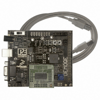
BOARD DEMO FOR 9S08 QB MCU
Manufacturer
Freescale Semiconductor
Type
MCUr
Specifications of DEMO9S08QB8
Contents
Board, Cable
Silicon Manufacturer
Freescale
Core Architecture
HCS08
Core Sub-architecture
HCS08
Silicon Core Number
MC9S08
Silicon Family Name
S08QB
Kit Contents
Board
Rohs Compliant
Yes
For Use With/related Products
MC9S08QB8
Lead Free Status / RoHS Status
Lead free / RoHS Compliant


3.5
3.5.1
10
Hardware Setup
First-Time Connection
Step 6.
The DEMO9S08QB8 may be connected to a PC through a USB port.
Connection steps are listed below in typical order:
1. Install the required software, as described in the previous section.
2. Make sure the jumpers for USB_PWR, 3V for VOLT_EN, and
3. Plug the USB cable A-M connector into a free USB port of the PC.
Figure 3-1: DEMOQE Logic Analyzer Application
REG_VDD for VDD_SELECT are installed.
http://www.pemicro.com/fixedlinks/demoQEtoolkit.html.
buzzer will vary as you rotate.
button at any time will turn off the buzzer sound and all the LEDs.
Optionally, you may run the DEMOQE Logic Analyzer Application
available in the DEMOQE toolkit on the CD. This PC-based
application graphs the IN0 and IN1 signals on the DEMOQE
board. If both J11 jumpers are installed, IN0 shows PTC0 and IN1
shows PTC1. Push button PTA2 three times after reset and turn
the potentiometer to change these signals. This application may
also be found at:
Pressing the PTA2 button a fourth time or pressing the PTA3
DEMO9S08QB8 User Manual
Related parts for DEMO9S08QB8
Image
Part Number
Description
Manufacturer
Datasheet
Request
R

Part Number:
Description:
Manufacturer:
STMicroelectronics
Datasheet:

Part Number:
Description:
DEMO BOARD FOR HMC6042/HMC1041Z
Manufacturer:
Honeywell Microelectronics & Precision Sensors

Part Number:
Description:
DEMO BOARD FOR HMC1042L/HMC1041Z
Manufacturer:
Honeywell Microelectronics & Precision Sensors
Datasheet:

Part Number:
Description:
KIT DEMO 4 SENSOR CHAN RS232
Manufacturer:
VTI Technologies
Datasheet:


Part Number:
Description:
DEMO: DC Power Supply, 32 Volts, 3 Amps
Manufacturer:
Tektronix
Part Number:
Description:
DEMO: Programmable DC Power Supply, 32 Volts, 3 Amps
Manufacturer:
Tektronix

Part Number:
Description:
Manufacturer:
Freescale Semiconductor, Inc
Datasheet:
Part Number:
Description:
Manufacturer:
Freescale Semiconductor, Inc
Datasheet:
Part Number:
Description:
Manufacturer:
Freescale Semiconductor, Inc
Datasheet:
Part Number:
Description:
Manufacturer:
Freescale Semiconductor, Inc
Datasheet:
Part Number:
Description:
Manufacturer:
Freescale Semiconductor, Inc
Datasheet:
Part Number:
Description:
Manufacturer:
Freescale Semiconductor, Inc
Datasheet:
Part Number:
Description:
Manufacturer:
Freescale Semiconductor, Inc
Datasheet:
Part Number:
Description:
Manufacturer:
Freescale Semiconductor, Inc
Datasheet: