ADUM1100EVAL Analog Devices Inc, ADUM1100EVAL Datasheet - Page 16
ADUM1100EVAL
Manufacturer Part Number
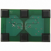
ADUM1100EVAL
Description
BOARD EVAL FOR ADUM1100
Manufacturer
Analog Devices Inc
Type
Digital Isolatorr
Datasheet
1.ADUM1100ARZ-RL7.pdf
(20 pages)
Specifications of ADUM1100EVAL
Design Resources
USB Cable Isolator Circuit (CN0159)
Contents
Evaluation Board
For Use With/related Products
ADUM1100
Lead Free Status / RoHS Status
Contains lead / RoHS non-compliant


ADuM1100
The impact of the slower input edge rates can also affect the
measured pulse width distortion as based on the input 50%
level. This impact can either increase or decrease the apparent
pulse width distortion depending on the relative magnitudes of
t
that leads to the largest increase in pulse width distortion. The
change in this case is given by
where:
PWD = |t
PWD’ = |t’
This adjustment in pulse width distortion is plotted as a
function of input rise/fall time in Figure 18.
PHL
, t
Δ
(t/0.8 V
PLH
PWD
–1
–2
–3
–4
, and PWD. The case of interest here is the condition
4
3
2
1
0
0
PLH
1
1
Figure 16. Typical Propagation Delay Change due to
Figure 17. Typical Propagation Delay Change due to
= PWD′ − PWD = Δ
PLH
Input Rise Time Variation (for V
Input Fall Time Variation (for V
1
− t
)(V − V
− t’
2
2
PHL
PHL
|
|.
3
3
ITH (L-H)
3.3V INPUT SIGNAL
INPUT RISE TIME (10%–90%, ns)
INPUT RISE TIME (10%–90%, ns)
4
4
− V
LH
5
5
ITH (H-L)
− Δ
5V INPUT SIGNAL
6
6
HL
DD1
DD1
), (for t = t
3.3V INPUT SIGNAL
5V INPUT SIGNAL
=
= 3.3 V and 5 V)
= 3.3 V and 5 V)
7
7
8
8
r
= t
f
9
9
)
10
10
Rev. H | Page 16 of 20
METHOD OF OPERATION, DC CORRECTNESS, AND
MAGNETIC FIELD IMMUNITY
The two coils in Figure 1 act as a pulse transformer. Positive
and negative logic transitions at the isolator input cause narrow
(2 ns) pulses to be sent via the transformer to the decoder. The
decoder is bistable and therefore either set or reset by the pulses
indicating input logic transitions. In the absence of logic transi-
tions at the input for more than ~1 μs, a periodic update pulse
of the appropriate polarity is sent to ensure dc correctness at the
output. If the decoder receives none of these update pulses for
more than about 5 μs, the input side is assumed to be unpowered
or nonfunctional, in which case the isolator output is forced to
a logic high state by the watchdog timer circuit.
The limitation on the magnetic field immunity of the
ADuM1100 is set by the condition in which induced voltage in
the transformer’s receiving coil is sufficiently large to either
falsely set or reset the decoder. The analysis that follows defines
the conditions under which this can occur. The 3.3 V operating
condition of the ADuM1100 is examined because it represents
the most susceptible mode of operation.
The pulses at the transformer output are greater than 1.0 V in
amplitude. The decoder has sensing thresholds at about 0.5 V,
therefore establishing a 0.5 V margin in which induced voltages
can be tolerated. The induced voltage induced across the
receiving coil is given by
where:
β is the magnetic flux density (gauss).
N is the number of turns in receiving coil.
r
n
Figure 18. Typical Pulse Width Distortion Adjustment due to Input Rise/Fall
is the radius of nth turn in receiving coil (cm).
V = (−dβ/dt) ∑π r
6
5
4
3
2
1
0
1
2
Time Variation (at V
INPUT RISE/FALL TIME (10%–90%, ns)
3
n
5V INPUT SIGNAL
2
, n = 1, 2, . . . , N
4
5
DD1
= 3.3 V and 5 V)
6
7
3.3V INPUT SIGNAL
8
9
10
Related parts for ADUM1100EVAL
Image
Part Number
Description
Manufacturer
Datasheet
Request
R

Part Number:
Description:
±1.7g Dual-Axis IMEMS Accelerometer Evaluation Board
Manufacturer:
Analog Devices Inc
Datasheet:

Part Number:
Description:
Inertial Sensor Evaluation System
Manufacturer:
Analog Devices Inc
Datasheet:
Part Number:
Description:
Manufacturer:
Analog Devices Inc
Datasheet:
Part Number:
Description:
Manufacturer:
Analog Devices Inc
Datasheet:
Part Number:
Description:
Manufacturer:
Analog Devices Inc
Datasheet:
Part Number:
Description:
Manufacturer:
Analog Devices Inc
Datasheet:
Part Number:
Description:
Manufacturer:
Analog Devices Inc
Datasheet:
Part Number:
Description:
Manufacturer:
Analog Devices Inc
Datasheet:
Part Number:
Description:
Manufacturer:
Analog Devices Inc
Datasheet:
Part Number:
Description:
Manufacturer:
Analog Devices Inc
Datasheet:
Part Number:
Description:
Manufacturer:
Analog Devices Inc
Datasheet:
Part Number:
Description:
Manufacturer:
Analog Devices Inc
Datasheet:
Part Number:
Description:
Manufacturer:
Analog Devices Inc
Datasheet: