EVAL-ADT7470EB Analog Devices Inc, EVAL-ADT7470EB Datasheet - Page 25
EVAL-ADT7470EB
Manufacturer Part Number
EVAL-ADT7470EB
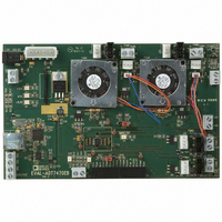
Description
BOARD EVALUATION FOR ADT7470
Manufacturer
Analog Devices Inc
Datasheet
1.ADT7470ARQZ.pdf
(40 pages)
Specifications of EVAL-ADT7470EB
Sensor Type
Temperature
Interface
SMBus (2-Wire/I²C)
Voltage - Supply
3 V ~ 5.5 V
Embedded
No
Utilized Ic / Part
ADT7470
Lead Free Status / RoHS Status
Contains lead / RoHS non-compliant


MANUAL FAN SPEED CONTROL
Manual fan speed control on the ADT7470 allows the user to
control the PWM duty cycle for each fan via the registers. The
ADt7470 powers-up in manual fan control mode, with all
PWM duty cycles set to maximum. The PWM Configuration
registers determine whether the fans are in manual or automatic
fan control mode.
SETTING THE PWM DUTY CYCLE
The ADT7470 allows the duty cycle of any PWM output to be
manually adjusted. This can be useful if users want to change
fan speed in software or want to adjust PWM duty cycle output
for test purposes. The PWM current duty cycle registers
(Register 0x32 to Register 0x35) can be written with 8-bit
values in manual fan speed control mode to manually adjust
the speeds of the cooling fans.
The PWM duty cycle for each output can be set anywhere from
0% to 100%, in steps of 0.39%.
Table 22.Fan Control Mode Configuration
Register/Bit
0x68 Bit[6]
0x68 Bit[7]
0x69 Bit[6]
0x69 Bit[7]
Mnenonic
BHVR2
BHVR1
BHVR4
BHVR3
Description
This bit determines fan behavior for PWM2 output.
0 = Manual mode (PWM2 duty cycle controlled in software).
1 = Fastest speed calculated by all temperatures control PWM2 (automatic fan control mode).
This bit determines fan behavior for PWM1 output.
0 = Manual mode (PWM1 duty cycle controlled in software).
1 = Fastest speed calculated by all temperatures control PWM1 (automatic fan control mode).
This bit determines fan behavior for PWM4 output.
0 = Manual mode (PWM4 duty cycle controlled in software).
1 = Fastest speed calculated by all temperatures control PWM4 (automatic fan control mode).
This bit determines fan behavior for PWM3 output.
0 = Manual mode (PWM3 duty cycle controlled in software).
1 = Fastest speed calculated by all temperatures control PWM3 (automatic fan control mode).
Rev. C | Page 25 of 40
The value to be programmed into the PWM Current Duty
Cycle registers can be calculated as follows:
Example 1: For a PWM Duty Cycle of 50%
Example 2: For a PWM Duty Cycle of 33%
Table 21. PWM Current Duty Cycle Registers
Register Address
0x32
0x33
0x34
0x35
Value (decimal) = Desired PWM duty cycle/0.39
Value (decimal) = 50/0.39 = 128 decimal
Value = 128 decimal or 80 hex
Value (decimal) = 33/0.39 = 85 decimal
Value = 85 decimal or 54 hex
Description
PWM1 duty cycle
PWM2 duty cycle
PWM3 duty cycle
PWM4 duty cycle
Default
0xFF (100%)
0xFF (100%)
0xFF (100%)
0xFF (100%)
ADT7470
Related parts for EVAL-ADT7470EB
Image
Part Number
Description
Manufacturer
Datasheet
Request
R


Part Number:
Description:
BOARD EVAL FOR SI270X-A
Manufacturer:
Silicon Laboratories Inc
Datasheet:

Part Number:
Description:
BUCK CONV REF DESIGN KIT IP1201
Manufacturer:
International Rectifier
Datasheet:
Part Number:
Description:
BOARD DEMO SYNC DUAL BUCK CNVTER
Manufacturer:
International Rectifier
Datasheet:
Part Number:
Description:
BOARD DEMO SYNC BUCK CONVETER
Manufacturer:
International Rectifier
Datasheet:

Part Number:
Description:
EVALBOARD/EB Omnidirectional microphone - Analog
Manufacturer:
Analog Devices
Datasheet:
Part Number:
Description:
EVALBOARD/EB Omnidirectional microphone - Analog
Manufacturer:
Analog Devices
Datasheet:


Part Number:
Description:
BOARD EVAL LED DRIVER LT3756
Manufacturer:
Linear Technology
Datasheet:

Part Number:
Description:
BOARD EVAL FOR AD7741/7742
Manufacturer:
Analog Devices Inc
Datasheet:

Part Number:
Description:
±1.7g Dual-Axis IMEMS Accelerometer Evaluation Board
Manufacturer:
Analog Devices Inc
Datasheet:

Part Number:
Description:
IC MULTIPLIER ANALOG 8-SOIC T/R
Manufacturer:
Analog Devices Inc
Datasheet:

Part Number:
Description:
IC ANALOG MULTIPLIER 8-DIP
Manufacturer:
Analog Devices Inc
Datasheet:
Part Number:
Description:
IC ANALOG MULTIPLIER 8-SOIC
Manufacturer:
Analog Devices Inc
Datasheet:
Part Number:
Description:
IC ANALOG MULTIPLIER 8-DIP
Manufacturer:
Analog Devices Inc
Datasheet: