EVAL-ADT7470EB Analog Devices Inc, EVAL-ADT7470EB Datasheet - Page 7
EVAL-ADT7470EB
Manufacturer Part Number
EVAL-ADT7470EB
Description
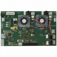
BOARD EVALUATION FOR ADT7470
Manufacturer
Analog Devices Inc
Datasheet
1.ADT7470ARQZ.pdf
(40 pages)
Specifications of EVAL-ADT7470EB
Sensor Type
Temperature
Interface
SMBus (2-Wire/I²C)
Voltage - Supply
3 V ~ 5.5 V
Embedded
No
Utilized Ic / Part
ADT7470
Lead Free Status / RoHS Status
Contains lead / RoHS non-compliant


FUNCTIONAL DESCRIPTION
GENERAL DESCRIPTION
The ADT7470 is a multichannel, pulse-width modulation
(PWM) fan controller and monitor for any system requiring
monitoring and cooling. The device communicates with the
system via a serial system management bus. The device has
a single address line for address selection (Pin 11), a serial
data line for reading and writing addresses and data (Pin 16),
and an input line for the serial clock (Pin 1). All control and
programming functions of the ADT7470 are performed over
the serial bus, which supports both SMBus and fast I
fications. In addition, an SMBALERT interrupt output is
provided to indicate out-of-limit conditions.
When the ADT7470 monitoring sequence is started, it cycles
through each fan tach input to measure fan speed. Measured
values from these inputs are stored in value registers. These
can be read out over the serial bus, or they can be automatically
compared with programmed limits stored in the limit registers.
The results of out-of-limit comparisons are stored in the status
registers, which can be read over the serial bus to flag out-of-
limit conditions. If fan speeds drop below preset levels or a
fan stalls, an interrupt is generated. Likewise, the ADT7470
can flag fan over speed conditions by using limits set in the
ADT7470 Monitoring Cycle
The monitoring cycle begins when a 1 is written to the start
bit (Bit 0) of Configuration Register 1 (Register 0x40). Each
fan tach input is monitored in turn, and, as each measurement
is completed, the result is automatically stored in the appropri-
ate value register. Multiple temperature channels can also be
monitored by clocking in temperatures using the TMP_IN
pin. The temperature measurement function is addressed
in hardware and requires no software intervention. The
monitoring cycle continues unless disabled by writing a 0
to Bit 7 of Configuration Register 1.
The rate of temperature measurement updates depends on
the nominal conversion rate of the TMP05/TMP06 temperature
fan tach maximum registers.
2
C speci-
Rev. C | Page 7 of 40
sensor (approximately 120 ms) and on the number of TMP05s
daisy-chained together. The total monitoring cycle time is the
temperature conversion time multiplied by the number of
temperature channels being monitored.
Fan tach measurements are taken in parallel and are not syn-
chronized with the temperature measurements in any way
CONFIGURATION REGISTER 1 (ADDRESS 0X40)
This register contains the STRT bit, Bit 0, which begins the
monitoring cycle on the ADT7470.
The SMBus timeout can be disabled , fast tach enabled, and
the registers locked, by writing to this register.
Control of high or low frequency fan drive, and the config-
uration for Pin 13, can be accessed via this register.
See Table 31 for more details.
CONFIGURATION REGISTER 2 (ADDRESS 0X74)
Writing a 1 to Bit 0 in this register puts the ADT7470 in
shutdown mode, which puts the part into a low current
consumption mode.
The PWM frequency for each fan is controlled via this register.
Fan speed measurement can be disabled for each fan by writing
to this register.
See Table 44 for more details.
ID REGISTERS
The ADT7470 has three read-only registers for identifying
the part and silicon revision.
The device ID register is located at address 0x3D, and is set
to 0x70.
The company ID register, located at address 0x3E, is set to 0x41.
The revision number register is at address 0x3F, and contains
the revision number of the ADT7470 silicon.
ADT7470
Related parts for EVAL-ADT7470EB
Image
Part Number
Description
Manufacturer
Datasheet
Request
R


Part Number:
Description:
BOARD EVAL FOR SI270X-A
Manufacturer:
Silicon Laboratories Inc
Datasheet:

Part Number:
Description:
BUCK CONV REF DESIGN KIT IP1201
Manufacturer:
International Rectifier
Datasheet:
Part Number:
Description:
BOARD DEMO SYNC DUAL BUCK CNVTER
Manufacturer:
International Rectifier
Datasheet:
Part Number:
Description:
BOARD DEMO SYNC BUCK CONVETER
Manufacturer:
International Rectifier
Datasheet:

Part Number:
Description:
EVALBOARD/EB Omnidirectional microphone - Analog
Manufacturer:
Analog Devices
Datasheet:
Part Number:
Description:
EVALBOARD/EB Omnidirectional microphone - Analog
Manufacturer:
Analog Devices
Datasheet:


Part Number:
Description:
BOARD EVAL LED DRIVER LT3756
Manufacturer:
Linear Technology
Datasheet:

Part Number:
Description:
BOARD EVAL FOR AD7741/7742
Manufacturer:
Analog Devices Inc
Datasheet:

Part Number:
Description:
±1.7g Dual-Axis IMEMS Accelerometer Evaluation Board
Manufacturer:
Analog Devices Inc
Datasheet:

Part Number:
Description:
IC MULTIPLIER ANALOG 8-SOIC T/R
Manufacturer:
Analog Devices Inc
Datasheet:

Part Number:
Description:
IC ANALOG MULTIPLIER 8-DIP
Manufacturer:
Analog Devices Inc
Datasheet:
Part Number:
Description:
IC ANALOG MULTIPLIER 8-SOIC
Manufacturer:
Analog Devices Inc
Datasheet:
Part Number:
Description:
IC ANALOG MULTIPLIER 8-DIP
Manufacturer:
Analog Devices Inc
Datasheet: