EVAL-ADT7470EB Analog Devices Inc, EVAL-ADT7470EB Datasheet - Page 8
EVAL-ADT7470EB
Manufacturer Part Number
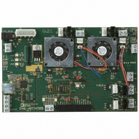
EVAL-ADT7470EB
Description
BOARD EVALUATION FOR ADT7470
Manufacturer
Analog Devices Inc
Datasheet
1.ADT7470ARQZ.pdf
(40 pages)
Specifications of EVAL-ADT7470EB
Sensor Type
Temperature
Interface
SMBus (2-Wire/I²C)
Voltage - Supply
3 V ~ 5.5 V
Embedded
No
Utilized Ic / Part
ADT7470
Lead Free Status / RoHS Status
Contains lead / RoHS non-compliant


ADT7470
GENERAL-PURPOSE I/O PINS (OPEN DRAIN)
The ADT7470 has four pins that can be configured as either general-purpose logic pins or as PWM outputs. Each GPIO pin has a
corresponding enable, direction, polarity and status bit.
Pin
GPIO1
GPIO2
GPIO3
GPIO4
To enable the PWM output on the ADT7470 as GPIOs, the enable bits in Register 0x7F must be set to 1.
Setting a direction bit to 1 in the GPIO configuration register makes the corresponding GPIO pin an output. Clearing the direction bit to
0 makes it an input.
Setting a polarity bit to 1 makes the corresponding GPIO pin active high. Clearing the polarity bit to 0 makes it active low.
When a GPIO pin is configured as an input, the corresponding bit in the GPIO status register is read-only and is set when the input is
asserted. When a GPIO pin is configured as an output, the corresponding bit in one of the GPIO status registers becomes read/write.
Setting this bit asserts the GPIO output. Note that whether a GPIO pin is configured as an input or as an output, asserted can be high or
low, depending on the setting of the polarity bit.
Function
Enable
Direction
Polarity
Status
Enable
Direction
Polarity
Status
Enable
Direction
Polarity
Status
Enable
Direction
Polarity
Status
Rev. C | Page 8 of 40
Register Address and Bit
0x7F [3]
0x80 [7]
0x80 [6]
0x81 [4]
0x7F [2]
0x80 [5]
0x80 [4]
0x81 [5]
0x7F [1]
0x80 [3]
0x80 [2]
0x81 [6]
0x7F [0]
0x80 [1]
0x80 [0]
0x81 [7]
Related parts for EVAL-ADT7470EB
Image
Part Number
Description
Manufacturer
Datasheet
Request
R


Part Number:
Description:
BOARD EVAL FOR SI270X-A
Manufacturer:
Silicon Laboratories Inc
Datasheet:

Part Number:
Description:
BUCK CONV REF DESIGN KIT IP1201
Manufacturer:
International Rectifier
Datasheet:
Part Number:
Description:
BOARD DEMO SYNC DUAL BUCK CNVTER
Manufacturer:
International Rectifier
Datasheet:
Part Number:
Description:
BOARD DEMO SYNC BUCK CONVETER
Manufacturer:
International Rectifier
Datasheet:

Part Number:
Description:
EVALBOARD/EB Omnidirectional microphone - Analog
Manufacturer:
Analog Devices
Datasheet:
Part Number:
Description:
EVALBOARD/EB Omnidirectional microphone - Analog
Manufacturer:
Analog Devices
Datasheet:


Part Number:
Description:
BOARD EVAL LED DRIVER LT3756
Manufacturer:
Linear Technology
Datasheet:

Part Number:
Description:
BOARD EVAL FOR AD7741/7742
Manufacturer:
Analog Devices Inc
Datasheet:

Part Number:
Description:
±1.7g Dual-Axis IMEMS Accelerometer Evaluation Board
Manufacturer:
Analog Devices Inc
Datasheet:

Part Number:
Description:
IC MULTIPLIER ANALOG 8-SOIC T/R
Manufacturer:
Analog Devices Inc
Datasheet:

Part Number:
Description:
IC ANALOG MULTIPLIER 8-DIP
Manufacturer:
Analog Devices Inc
Datasheet:
Part Number:
Description:
IC ANALOG MULTIPLIER 8-SOIC
Manufacturer:
Analog Devices Inc
Datasheet:
Part Number:
Description:
IC ANALOG MULTIPLIER 8-DIP
Manufacturer:
Analog Devices Inc
Datasheet: