M68MULTILINK08 Freescale Semiconductor, M68MULTILINK08 Datasheet - Page 40
M68MULTILINK08
Manufacturer Part Number
M68MULTILINK08
Description
PROGRAMMER LOW COST 68HC908
Manufacturer
Freescale Semiconductor
Type
In Circuit Debuggerr
Datasheet
1.M68MULTILINK08.pdf
(52 pages)
Specifications of M68MULTILINK08
Contents
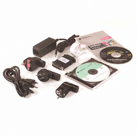
In-Circuit Programmer, Emulator, Debugger, CodeWarrior Dev. Studio for HC08, Power Supply
For Use With/related Products
68HC908 FLASH MCUs
Lead Free Status / RoHS Status
Contains lead / RoHS non-compliant


MON08 MULTILINK
40
Class IV
In this configuration, because the software does not directly control power to
the processor, the user will be prompted to turn the processor’s power supply
on and off. Turning off the power supply is necessary in order to be able to pass
the initial security mode check and access the flash on the processor. A simple
reset is not enough; to pass the security check, you must first force the
processor to encounter a POR (power-on reset) which requires the processor’s
voltage to dip below 0.1v. Once security has been passed, resetting the device
power supply on and off. The use will also be prompted to turn power
on and off to reset the target processor, as the PC doesn’t have control
of the target reset. Turning off the power supply is necessary mainly to
be able to pass the initial security mode check and access the flash on
the processor. A simple reset is not enough; to pass the security check,
you must first force the processor to encounter a POR (power-on reset)
which requires that the processor’s voltage dip below 0.1v. Once
security has been passed, resetting the device or re-entering the
software should be easier. This configuration can be specified at startup
in the software by using the NODTR command-line parameter;
otherwise the software will remember the hardware configuration from
session to session. The Class III selection also applies to use of the ICS
board with the two-pin blank part programming connector.
Custom Board (no ICS) with MON08 serial port circuitry and
additional auto-reset circuit built in. In this configuration, the ICS
board is not used at all. The user must provide a serial port connection
from the PC and all hardware configuration necessary to force the
processor into MON08 mode upon reset. In addition, the user must
include an extra circuit which allows the reset line of the processor to
be driven low from the DTR line of the serial port connector (Pin 4 on a
DB9). The following diagram shows the additional connection needed
to reset from a DB9 serial connector.
Figure 4-37: Additional Connection To Reset From DB9
Freescale Semiconductor, Inc.
For More Information On This Product,
Go to: www.freescale.com
P&E
MON08 Multilink User Manual
Microcomputer
Systems, Inc.
Related parts for M68MULTILINK08
Image
Part Number
Description
Manufacturer
Datasheet
Request
R

Part Number:
Description:
Manufacturer:
Freescale Semiconductor, Inc
Datasheet:
Part Number:
Description:
Manufacturer:
Freescale Semiconductor, Inc
Datasheet:
Part Number:
Description:
Manufacturer:
Freescale Semiconductor, Inc
Datasheet:
Part Number:
Description:
Manufacturer:
Freescale Semiconductor, Inc
Datasheet:
Part Number:
Description:
Manufacturer:
Freescale Semiconductor, Inc
Datasheet:
Part Number:
Description:
Manufacturer:
Freescale Semiconductor, Inc
Datasheet:
Part Number:
Description:
Manufacturer:
Freescale Semiconductor, Inc
Datasheet:
Part Number:
Description:
Manufacturer:
Freescale Semiconductor, Inc
Datasheet:
Part Number:
Description:
Manufacturer:
Freescale Semiconductor, Inc
Datasheet:
Part Number:
Description:
Manufacturer:
Freescale Semiconductor, Inc
Datasheet:
Part Number:
Description:
Manufacturer:
Freescale Semiconductor, Inc
Datasheet:
Part Number:
Description:
Manufacturer:
Freescale Semiconductor, Inc
Datasheet:
Part Number:
Description:
Manufacturer:
Freescale Semiconductor, Inc
Datasheet:
Part Number:
Description:
Manufacturer:
Freescale Semiconductor, Inc
Datasheet:
Part Number:
Description:
Manufacturer:
Freescale Semiconductor, Inc
Datasheet: