MC56F8323EVM Freescale Semiconductor, MC56F8323EVM Datasheet - Page 138
MC56F8323EVM
Manufacturer Part Number
MC56F8323EVM
Description
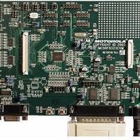
KIT EVALUATION FOR MC56F8323
Manufacturer
Freescale Semiconductor
Type
DSPr
Datasheets
1.CWH-UTP-ONCE-HE.pdf
(2 pages)
2.MC56F8323EVM.pdf
(72 pages)
3.MC56F8323EVME.pdf
(140 pages)
Specifications of MC56F8323EVM
Contents
Module and Misc Hardware
Processor To Be Evaluated
MC56F8322 and MC56F8323
Data Bus Width
16 bit
Interface Type
RS-232
For Use With/related Products
MC56F8322, MC56F8323
Lead Free Status / RoHS Status
Contains lead / RoHS non-compliant


12.3 Power Distribution and I/O Ring Implementation
Figure 12-1
contains two internal power regulators. One of them is powered from the V
be turned off. This regulator controls power to the internal clock generation circuitry. The other regulator
is powered from the V
peripherals and the internal memories. This regulator can be turned off, if an external V
is externally applied to the V
In summary, the entire chip can be supplied from a single 3.3 volt supply if the large core regulator is
enabled. If the regulator is not enabled, a dual supply 3.3V/2.5V configuration can also be used.
Notes:
138
•
•
•
•
•
•
•
•
OCS
V
Because the device’s output signals have fast rise and fall times, PCB trace lengths should be minimal
Consider all device loads as well as parasitic capacitance due to PCB traces when calculating capacitance.
This is especially critical in systems with higher capacitive loads that could create higher transient currents
in the V
Take special care to minimize noise levels on the V
Designs that utilize the TRST pin for JTAG port or EOnCE module functionality (such as development or
debugging systems) should allow a means to assert TRST whenever RESET is asserted, as well as a means
to assert TRST independently of RESET. Designs that do not require debugging functionality, such as
consumer products, should tie these pins together.
Because the Flash memory is programmed through the JTAG/EOnCE port, the designer should provide an
interface to this port to allow in-circuit Flash programming
Flash, RAM and internal logic are powered from the core regulator output
V
All circuitry, analog and digital, shares a common V
DDA_OSC_PLL
PP
1 and V
illustrates the general power control incorporated in the 56F8323/56F8123. This chip
DD
and V
PP
REG
2 are not connected in the customer system
DD_IO
SS
circuits.
ROSC
CAP
pins and provides power to all of the internal digital logic of the core, all
pins.
Figure 12-1 Power Management
56F8323 Technical Data, Rev. 17
REG
V
DD
CORE
REF
SS
V
SS
, V
V
bus
CAP
DDA
and V
I/O
SSA
pins
DDA_OSC_PLL
V
V
SSA_ADC
ADC
DDA_ADC
Freescale Semiconductor
DD_CORE
pin and cannot
V
V
V
V
V
REFH
REFP
REFMID
REFN
REFLO
Preliminary
voltage
Related parts for MC56F8323EVM
Image
Part Number
Description
Manufacturer
Datasheet
Request
R

Part Number:
Description:
Manufacturer:
Freescale Semiconductor, Inc
Datasheet:
Part Number:
Description:
Manufacturer:
Freescale Semiconductor, Inc
Datasheet:
Part Number:
Description:
Manufacturer:
Freescale Semiconductor, Inc
Datasheet:
Part Number:
Description:
Manufacturer:
Freescale Semiconductor, Inc
Datasheet:
Part Number:
Description:
Manufacturer:
Freescale Semiconductor, Inc
Datasheet:
Part Number:
Description:
Manufacturer:
Freescale Semiconductor, Inc
Datasheet:
Part Number:
Description:
Manufacturer:
Freescale Semiconductor, Inc
Datasheet:
Part Number:
Description:
Manufacturer:
Freescale Semiconductor, Inc
Datasheet:
Part Number:
Description:
Manufacturer:
Freescale Semiconductor, Inc
Datasheet:
Part Number:
Description:
Manufacturer:
Freescale Semiconductor, Inc
Datasheet:
Part Number:
Description:
Manufacturer:
Freescale Semiconductor, Inc
Datasheet:
Part Number:
Description:
Manufacturer:
Freescale Semiconductor, Inc
Datasheet:
Part Number:
Description:
Manufacturer:
Freescale Semiconductor, Inc
Datasheet:
Part Number:
Description:
Manufacturer:
Freescale Semiconductor, Inc
Datasheet:
Part Number:
Description:
Manufacturer:
Freescale Semiconductor, Inc
Datasheet: