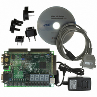
HW-SPAR3-SK-UNI-G Xilinx Inc, HW-SPAR3-SK-UNI-G Datasheet - Page 48

HW-SPAR3-SK-UNI-G
Manufacturer Part Number
HW-SPAR3-SK-UNI-G
Description
KIT STARTER SPARTAN-3
Manufacturer
Xilinx Inc
Series
Spartan-3r
Type
FPGA Configurationr
Datasheet
1.HW-SPAR3-SK-UNI-G.pdf
(64 pages)
Specifications of HW-SPAR3-SK-UNI-G
Contents
Board, Cable, Software, Datasheets and User Manual
For Use With/related Products
Spartan-3
Lead Free Status / RoHS Status
Lead free / RoHS Compliant
Other names
122-1521
Available stocks
Company
Part Number
Manufacturer
Quantity
Price
Table 13-1: Expansion Connector Features
48
Connector
A1
A2
B1
Pin 40
R
Pin 39
User I/O
32
34
34
Each port offers some ability to program the FPGA on the Spartan-3 Starter Kit Board. For
example, port A1 provides additional logic to drive the FPGA and Platform Flash JTAG
chain. Similarly, ports A2 and B1 provide connections for Master or Slave Serial mode
configuration. Finally, port B1 also offers Master or Slave Parallel configuration mode.
Each 40-pin expansion header, shown in
Pin 1 on each connector is always GND. Similarly, pin 2 is always the +5V DC output from
the switching power supply. Pin 3 is always the output from the +3.3V DC regulator.
The pinout information for each connector appears below. The tables include the
connections between the FPGA and the expansion connectors plus the signal names used
in the detailed schematic in
Data[7:0] to IC10 only
Figure 13-2: 40-pin Expansion Connector
OE#, WE#
Address
SRAM
www.xilinx.com
Figure
JTAG
√
A-1.
Chapter 13: Expansion Connectors and Boards
Serial Configuration
Figure
Pin 3: +3.3V
Spartan-3 FPGA Starter Kit Board User Guide
Pin 4
13-2, uses 0.1-inch (100 mil) DIP spacing.
√
√
Pin 1: GND
Pin 2: VU
+5V
Parallel Configuration
UG130 (v1.2) June 20, 2008
Pin 39
Pin 40
UG130_c12_02_042504
√


