TOOLSTICK542PP Silicon Laboratories Inc, TOOLSTICK542PP Datasheet - Page 140
TOOLSTICK542PP
Manufacturer Part Number
TOOLSTICK542PP
Description
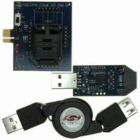
PLATFORM PROG TOOLSTICK F542
Manufacturer
Silicon Laboratories Inc
Series
ToolStickr
Type
Microcontroller Programmerr
Specifications of TOOLSTICK542PP
Contents
2 Boards and USB Connecting Cable
Processor To Be Evaluated
C8051F542
Interface Type
USB
Operating Supply Voltage
2.7 V to 3.6 V
Lead Free Status / RoHS Status
Lead free / RoHS Compliant
For Use With/related Products
C8051F542
Lead Free Status / Rohs Status
Lead free / RoHS Compliant
Other names
336-1718


C8051F54x
17.3. Clock Multiplier
The Clock Multiplier generates an output clock which is 4 times the input clock frequency scaled by a pro-
grammable factor of 1, 2/3, 2/4 (or 1/2), 2/5, 2/6 (or 1/3), or 2/7. The Clock Multiplier’s input can be
selected from the external oscillator, or the internal or external oscillators divided by 2. This produces three
possible base outputs which can be scaled by a programmable factor: Internal Oscillator x 2, External
Oscillator x 2, or External Oscillator x 4. See Section 17.1 on page 135 for details on system clock selec-
tion.
The Clock Multiplier is configured via the CLKMUL register (SFR Definition 17.5). The procedure for con-
figuring and enabling the Clock Multiplier is as follows:
1. Reset the Multiplier by writing 0x00 to register CLKMUL.
2. Select the Multiplier input source via the MULSEL bits.
3. Select the Multiplier output scaling factor via the MULDIV bits
4. Enable the Multiplier with the MULEN bit (CLKMUL | = 0x80).
5. Delay for >5 µs.
6. Initialize the Multiplier with the MULINIT bit (CLKMUL | = 0xC0).
7. Poll for MULRDY > 1.
Important Note: When using an external oscillator as the input to the Clock Multiplier, the external source
must be enabled and stable before the Multiplier is initialized. See “17.4. External Oscillator Drive Circuit”
on page 142 for details on selecting an external oscillator source.
The Clock Multiplier allows faster operation of the CIP-51 core and is intended to generate an output fre-
quency between 25 and 50 MHz. The clock multiplier can also be used with slow input clocks. However, if
the clock is below the minimum Clock Multiplier input frequency (FCM
of four fast pulses followed by a long delay until the next input clock rising edge. The average frequency of
the output is equal to 4x the input, but the instantaneous frequency may be faster. See Figure 17.2 below
for more information.
140
if F
if F
CM
CM
in
in
< F
>= F
F
F
F
F
CM in
CM out
CM in
CM out
CM min
CM min
Figure 17.2. Example Clock Multiplier Output
Rev. 1.1
min
), the generated clock will consist
Related parts for TOOLSTICK542PP
Image
Part Number
Description
Manufacturer
Datasheet
Request
R

Part Number:
Description:
KIT TOOL EVAL SYS IN A USB STICK
Manufacturer:
Silicon Laboratories Inc
Datasheet:

Part Number:
Description:
TOOLSTICK DEBUG ADAPTER
Manufacturer:
Silicon Laboratories Inc
Datasheet:

Part Number:
Description:
TOOLSTICK BASE ADAPTER
Manufacturer:
Silicon Laboratories Inc
Datasheet:

Part Number:
Description:
TOOLSTICK DAUGHTER CARD
Manufacturer:
Silicon Laboratories Inc
Datasheet:

Part Number:
Description:
TOOLSTICK DAUGHTER CARD
Manufacturer:
Silicon Laboratories Inc
Datasheet:

Part Number:
Description:
TOOLSTICK DAUGHTER CARD
Manufacturer:
Silicon Laboratories Inc
Datasheet:

Part Number:
Description:
TOOLSTICK DAUGHTER CARD
Manufacturer:
Silicon Laboratories Inc
Datasheet:

Part Number:
Description:
KIT STARTER TOOLSTICK
Manufacturer:
Silicon Laboratories Inc
Datasheet:

Part Number:
Description:
KIT UNIVERSITY TOOLSTICK STARTER
Manufacturer:
Silicon Laboratories Inc
Datasheet:

Part Number:
Description:
DAUGHTER CARD TOOLSTICK F330
Manufacturer:
Silicon Laboratories Inc
Datasheet:

Part Number:
Description:
CARD DAUGHTER UNIVRSTY TOOLSTICK
Manufacturer:
Silicon Laboratories Inc
Datasheet:

Part Number:
Description:
DAUGHTER CARD TOOLSTICK F582
Manufacturer:
Silicon Laboratories Inc
Datasheet:

Part Number:
Description:
DAUGHTER CARD TOOLSTICK F500
Manufacturer:
Silicon Laboratories Inc
Datasheet:

Part Number:
Description:
DAUGHTER CARD TOOLSTICK F540
Manufacturer:
Silicon Laboratories Inc
Datasheet:

Part Number:
Description:
DAUGHTER CARD TOOLSTICK F560
Manufacturer:
Silicon Laboratories Inc
Datasheet: