TOOLSTICK542PP Silicon Laboratories Inc, TOOLSTICK542PP Datasheet - Page 249
TOOLSTICK542PP
Manufacturer Part Number
TOOLSTICK542PP
Description
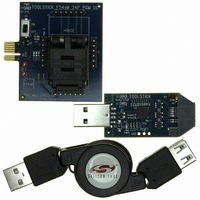
PLATFORM PROG TOOLSTICK F542
Manufacturer
Silicon Laboratories Inc
Series
ToolStickr
Type
Microcontroller Programmerr
Specifications of TOOLSTICK542PP
Contents
2 Boards and USB Connecting Cable
Processor To Be Evaluated
C8051F542
Interface Type
USB
Operating Supply Voltage
2.7 V to 3.6 V
Lead Free Status / RoHS Status
Lead free / RoHS Compliant
For Use With/related Products
C8051F542
Lead Free Status / Rohs Status
Lead free / RoHS Compliant
Other names
336-1718


24. Programmable Counter Array
The Programmable Counter Array (PCA0) provides enhanced timer functionality while requiring less CPU
intervention than the standard 8051 counter/timers. The PCA consists of a dedicated 16-bit counter/timer
and six 16-bit capture/compare modules. Each capture/compare module has its own associated I/O line
(CEXn) which is routed through the Crossbar to Port I/O when enabled. The counter/timer is driven by a
programmable timebase that can select between six sources: system clock, system clock divided by four,
system clock divided by twelve, the external oscillator clock source divided by 8, Timer 0 overflows, or an
external clock signal on the ECI input pin. Each capture/compare module may be configured to operate
independently in one of six modes: Edge-Triggered Capture, Software Timer, High-Speed Output, Fre-
quency Output, 8 to 11-Bit PWM, or 16-Bit PWM (each mode is described in Section
“24.3. Capture/Compare Modules” on page 252). The external oscillator clock option is ideal for real-time
clock (RTC) functionality, allowing the PCA to be clocked by a precision external oscillator while the inter-
nal oscillator drives the system clock. The PCA is configured and controlled through the system controller's
Special Function Registers. The PCA block diagram is shown in Figure 24.1
Important Note: The PCA Module 5 may be used as a watchdog timer (WDT), and is enabled in this mode
following a system reset. Access to certain PCA registers is restricted while WDT mode is enabled .
See Section 24.4 for details.
Capture/Compare
Module 0
SYSCLK/12
SYSCLK/4
Timer 0 Overflow
ECI
SYSCLK
External Clock/8
Capture/Compare
Module 1
CLOCK
MUX
PCA
Figure 24.1. PCA Block Diagram
16-Bit Counter/Timer
Capture/Compare
Module 2
Crossbar
Rev. 1.1
Port I/O
Capture/Compare
Module 3
Capture/Compare
Module 4
C8051F54x
Capture/Compare
Module 5 / WDT
249
Related parts for TOOLSTICK542PP
Image
Part Number
Description
Manufacturer
Datasheet
Request
R

Part Number:
Description:
KIT TOOL EVAL SYS IN A USB STICK
Manufacturer:
Silicon Laboratories Inc
Datasheet:

Part Number:
Description:
TOOLSTICK DEBUG ADAPTER
Manufacturer:
Silicon Laboratories Inc
Datasheet:

Part Number:
Description:
TOOLSTICK BASE ADAPTER
Manufacturer:
Silicon Laboratories Inc
Datasheet:

Part Number:
Description:
TOOLSTICK DAUGHTER CARD
Manufacturer:
Silicon Laboratories Inc
Datasheet:

Part Number:
Description:
TOOLSTICK DAUGHTER CARD
Manufacturer:
Silicon Laboratories Inc
Datasheet:

Part Number:
Description:
TOOLSTICK DAUGHTER CARD
Manufacturer:
Silicon Laboratories Inc
Datasheet:

Part Number:
Description:
TOOLSTICK DAUGHTER CARD
Manufacturer:
Silicon Laboratories Inc
Datasheet:

Part Number:
Description:
KIT STARTER TOOLSTICK
Manufacturer:
Silicon Laboratories Inc
Datasheet:

Part Number:
Description:
KIT UNIVERSITY TOOLSTICK STARTER
Manufacturer:
Silicon Laboratories Inc
Datasheet:

Part Number:
Description:
DAUGHTER CARD TOOLSTICK F330
Manufacturer:
Silicon Laboratories Inc
Datasheet:

Part Number:
Description:
CARD DAUGHTER UNIVRSTY TOOLSTICK
Manufacturer:
Silicon Laboratories Inc
Datasheet:

Part Number:
Description:
DAUGHTER CARD TOOLSTICK F582
Manufacturer:
Silicon Laboratories Inc
Datasheet:

Part Number:
Description:
DAUGHTER CARD TOOLSTICK F500
Manufacturer:
Silicon Laboratories Inc
Datasheet:

Part Number:
Description:
DAUGHTER CARD TOOLSTICK F540
Manufacturer:
Silicon Laboratories Inc
Datasheet:

Part Number:
Description:
DAUGHTER CARD TOOLSTICK F560
Manufacturer:
Silicon Laboratories Inc
Datasheet: