H5S-WB2 Omron, H5S-WB2 Datasheet - Page 25
H5S-WB2
Manufacturer Part Number
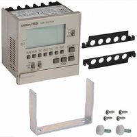
H5S-WB2
Description
TIMER DIGITAL WEEKLY 100-240VAC
Manufacturer
Omron
Series
H5Sr
Specifications of H5S-WB2
Supply Voltage
100 V to 240 V
Current Rating (max)
100 mA
Product
Digital Timer
Termination Style
Screw
No. Of Digits / Alpha
2
Meter Function
Counter
Supply Voltage Max
240VAC
Supply Voltage Min
100VAC
Lead Free Status / RoHS Status
Lead free / RoHS Compliant
Lead Free Status / RoHS Status
Lead free / RoHS Compliant, Lead free / RoHS Compliant
Other names
Z2504


Period of Season (F9)
Switching seasons
One group of programs is automatically switched to another,
according to the seasons set in initial setting mode.*
* The season switching functions apply only to weekly programs, not
yearly programs.
Programming a season
Press
Different weekly programs can be set for each season.
Next Operation Display (F1)
The order of the output channels for which the next operation (the
next ON or OFF time) is set can be selected for the sub-display.
This function is useful when an operation in a particular circuit is to
be monitored.
Parameters
Note: 1. Circuits 3 and 4 are not displayed for 2-circuit models.
Setting method
Shaded portion indicates
blinking of the indicator.
Note:
• The following is set as the default period of season.
• If overlapping periods are set, the priority becomes A<B<C<D.
• All outputs are OFF in the weekly program for all dates that do not come in
Weekly, 2 Circuits
Shaded portion indicates
blinking of the indicator.
only 1
only 2 - - - - - - - - - - Displays the next operation for circuit 2 only.
only 3 - - - - - - - - - - Displays the next operation for circuit 3 only.
only 4 - - - - - - - - - - Displays the next operation for circuit 4 only.
all 1234 - - - - - - - - Displays the next operation for all circuits.
A: 1.1 to 12.31 (1/1 to 12/31)
B to D: --.-- to --.-- (no setting)
*The “C” and “D” indications are not displayed in 2-circuit models.
For example, setting A (1/1 to 12/31) and B (4/1 to 9/30) will result in the
following: 1/1 to 3/31: A, 4/1 to 9/30: B, 10/1 to 12/31: A.
any period.
2.
TIME ADJ
- - - - - - - - - - Displays the next operation for circuit 1 only.
The inverted characters
in program setting mode to switch seasons.
Yearly, 2 Circuits
1. Press
2. Press
3. Press
4. Press
1. Select one of the parameters using
2. Press
season.
The display then changes to the start
period of season input screen. Press
date.
The display then changes to the end
period of season input screen. Press
date.
M
M
h
indicate the default.
or
or
or
WRITE
WRITE
WRITE
WRITE
h
m
D
D
Yearly, 4 Circuits
.
or
to designate the starting
to designate the ending
m
to enter the setting.
to enter the setting.
to enter the setting.
to enter the setting.
to select the desired
Date Format Selection (F5)
The displayed date format is selectable between “month. day” and
“day. month”.
Parameters
Note:
Setting method
Summer Time (DST) Adjustment (F6)
Manual or automatic summer time adjustment can be selected.
Parameters
Note:
Setting method
Yearly, 2 Circuits
dd.nn: “day. month”
Shaded portion indicates
blinking of the indicator.
Yearly, 2 Circuits
Shaded portion indicates
blinking of the indicator.
mm.dd
auto: Automatic adjustment (Select summer time schedule in F7.)
off
: Manual adjustment
: “month. day”
The inverted characters
The inverted characters
Yearly, 4 Circuits
Yearly, 4 Circuits
1. Press
2. Press
1. Press
2. Press
indicate the default.
indicate the default.
parameters.
parameters.
WRITE
WRITE
h
h
or
or
m
m
to enter the setting.
to enter the setting.
to select one of the
to select one of the
H5S
25
Related parts for H5S-WB2
Image
Part Number
Description
Manufacturer
Datasheet
Request
R


Part Number:
Description:
TIMER WEEKLY DGTL PRESET DIN MNT
Manufacturer:
Omron
Datasheet:

Part Number:
Description:
TIMER YEARLY 4CIRCT 100-240V SMD
Manufacturer:
Omron
Datasheet:

Part Number:
Description:
TIMER DIGITAL WEEKLY 100-240VAC
Manufacturer:
Omron
Datasheet:

Part Number:
Description:
TIMER WEEKLY DGTL PRESET DIN MNT
Manufacturer:
Omron
Datasheet:

Part Number:
Description:
Timer, Weekly, Surface/Track mounting, 2 Circuit Outputs, 100to240vAC Supply Voltage
Manufacturer:
Omron Automation
Datasheet:
Part Number:
Description:
Timer, Yearly timer, 2-circuit (SPST-NO), 100-240VAC
Manufacturer:
Omron Automation
Datasheet:
Part Number:
Description:
G6S-2GLow Signal Relay
Manufacturer:
Omron Corporation
Datasheet:
Part Number:
Description:
Compact, Low-cost, SSR Switching 5 to 20 A
Manufacturer:
Omron Corporation
Datasheet: