TL71 Fluke Electronics, TL71 Datasheet - Page 17
TL71
Manufacturer Part Number
TL71
Description
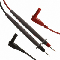
TEST LEAD SET 10A
Manufacturer
Fluke Electronics
Datasheet
1.I400.pdf
(72 pages)
Specifications of TL71
Current Rating
10A
Termination
Banana Plug, Sheathed, Right Angle
Color
Black and Red - Plugs and Wire; Gray - Probes
Ratings
CAT IV, 600V; CAT III, 1000V
Wire Insulation Material
Silicone
Includes
Pin Tip
For Use With
614-1085 - MULTIMETER INDUSTRIAL 1000V CATFLUKE-116 - MULTIMETER HVAC TRUE RMS614-1061 - DMM TRUE RMS 50000CNT W/BCKLGHT614-1020 - DMM TRE RMS W/BCKLGT 6000CNT DIS
Lead Free Status / RoHS Status
Lead free / RoHS Compliant
Voltage - Max
-
Impedance
-
Cable Length
-
Other names
1274382
614-1054
614-1054
Available stocks
Company
Part Number
Manufacturer
Quantity
Price

Part Number:
TL71025
Manufacturer:
TI/德州仪器
Quantity:
20 000
Company:
Part Number:
TL7102BC
Manufacturer:
MOLEX
Quantity:
26 000
Company:
Part Number:
TL710CN
Manufacturer:
ALTERA
Quantity:
5 510
Part Number:
TL710CP
Manufacturer:
TI/德州仪器
Quantity:
20 000
Part Number:
TL712CD
Manufacturer:
TI/德州仪器
Quantity:
20 000
Part Number:
TL712CDR
Manufacturer:
TI/德州仪器
Quantity:
20 000
Part Number:
TL712CP
Manufacturer:
TI/德州仪器
Quantity:
20 000


Specifications – 117 and 115 DMMs
Features – 117 and 115 DMMs
For more information and detailed specifications, go to www.fluke.com/dmm
Recommended accessories – 117 and 115 DMMs
Volts ac/dc
Current ac/dc
Resistance
Capacitance
Frequency
Diode
Feature
VoltAlert
AutoVolt/LoZ
Analog bargraph
Large backlit digital display
True-rms for accurate measurements on non-linear loads
Min/Max recording
Display hold
3-1⁄2 digits
6000 counts
CAT III 600 V safety rated
Function
Meter Hanger
See page 71
ToolPak
Fluke 117 and 115 True-rms
™
™
Designed for commercial electricians
SureGrip Industrial
Test Lead Set
See page 61
TL0
and field service technicians
Digital Multimeters
Fluke 117
The Fluke 117 is the ideal meter for demanding settings
like commercial buildings, hospitals and schools. The 117
includes integrated non-contact voltage detection to help
get the job done faster.
The 117 features include:
•
•
•
•
•
•
•
•
•
Fluke 115
The new Fluke 115 is the solution for a wide variety of
electrical and electronic testing applications.
The 115 features include:
•
•
•
•
VoltAlert
voltage detection
AutoVolt feature for automatic ac/dc voltage selection
LoZ: low input impedance prevents false readings due
to “ghost voltage”
Large display and white LED backlight to work in
poorly lit areas more effectively
Compact design for one-handed operation
Min/Max/Average to record signal fluctuations
Compatible with optional magnetic hanger (ToolPak
for hands free operation
Current measurement 20 A (30 seconds momentary;
10 A continuous)
Resistance, continuity, frequency and capacitance
Large display and white LED backlight to work in poor-
ly lit areas more effectively
Compact ergonomic design for
one-handed operation
Min/Max/Average to record signal
fluctuations
Resistance, continuity, frequency and capacitance
Range and resolution
1 nF to 9,999 µF
5 Hz to 50 kHz
40 MW
™
600 V
10 A
2 V
Technology for integrated non-contact
Carrying Case
See page 70
C50
117
•
•
•
•
•
•
•
•
•
•
Best accuracy
0.5 % + 2
0.9 % + 2
0.9 % + 2
1.0 % + 3
1.9 % + 2
0.1 % + 2
115
•
•
•
•
•
•
•
•
™
)
117/ Electrician’s
Combo Kit
•
•
•
•
•
Application note, literature code
1260729:
Why true-rms?
If you’re
measuring
non-linear
loads like
variable
frequency
drives, solid
state heater
drives, or
electronics,
you need a
true-rms tool
to get accurate
readings.
Average
responding meters will read low,
up to 30 or 40 percent low in some
cases. This application note explains
what true-rms is and when you need
it in your test tool.
Want to read more? Download this
and other application notes at
www.fluke.com/library
117 True-rms digital multimeter
with non-contact voltage detection
New!
with shoulder strap
322 Compact clamp meter
TL75 Hard Point Test Lead Set
ToolPak Magnetic Meter Hanging
Strap
Included accessories
TL75 Test leads, holster, users
manual and 9 V battery (installed).
Ordering information
Fluke-117
Fluke-117/322 Electrician’s
Fluke-115
C115 Deluxe carrying case
Digital Multimeters
Multimeter with
Non-Contact Voltage
Combo Kit
Multimeter
current clamp for accurate readings
F r o m t h e F l u k e D i g i t a l L i b r a r y @ w w w . f l u k e . c o m / l i b r a r y
Non-linear loads need a true-rms
Why true-rms?
Figure 1. One current—two readings. Which do you trust? The branch circuit above feeds a
non-linear load with distorted current. The true-rms clamp reads correctly but the average
responding clamp reads low by 32 percent.
Introduction
Troubleshooting the electrical
service feeding adjustable
speed motor loads can be diffi-
cult if you don’t have the right
tools. New solid state motor
drives and heating controls
often conduct non-sinusoidal
(distorted) current. In other
words, the current occurs in
short pulses rather than the
smooth sine wave drawn
by a standard induction motor.
The current wave shape can
have a drastic effect on a
current clamp reading.
types of current clamps
commonly available: “average
responding” and “true-rms.”
The average responding units
are widely used and are usually
Basically, there are two
lower cost. They give correct
readings for linear loads such
as standard induction motors,
resistance heaters, and incan-
descent lights. But when loads
are non-linear, containing
semiconductors, the average
responding meters typically
read low. Worst case non-
linear loads include small
adjustable speed drives (5 hp
or less) connected line to line
across two phases of a 480 V,
three-phase system, solid state
heater controls connected
single phase to 240 V, or
computers connected to 120 V.
When troubleshooting a branch
circuit that suffers from circuit
breaker tripping (or fuse blow-
ing), the cause of the trouble
Application Note
can usually be separated into
one of three categories:
1. Too much current.
2. Too much heat in the
3. Faulty circuit breaker
Your first instinct will probably
be to measure the current with
a current clamp while the load
is on. If the current is within
the circuit rating, you may be
tempted to replace the circuit
breaker.
Figure 2. A computer load.
Non-linear loads that cause
measurement errors.
Figure 3. An adjustable speed motor load.
electrical enclosure.
(or fuse).
17
17