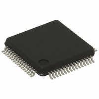
STM32F101RBT6 STMicroelectronics, STM32F101RBT6 Datasheet - Page 77

STM32F101RBT6
Manufacturer Part Number
STM32F101RBT6
Description
MCU ARM 128KB FLASH/TIMER 64LQFP
Manufacturer
STMicroelectronics
Series
STM32r
Specifications of STM32F101RBT6
Core Processor
ARM® Cortex-M3™
Core Size
32-Bit
Speed
36MHz
Connectivity
I²C, IrDA, LIN, SPI, UART/USART
Peripherals
DMA, PDR, POR, PVD, PWM, Temp Sensor, WDT
Number Of I /o
51
Program Memory Size
128KB (128K x 8)
Program Memory Type
FLASH
Ram Size
16K x 8
Voltage - Supply (vcc/vdd)
2 V ~ 3.6 V
Data Converters
A/D 16x12b
Oscillator Type
Internal
Operating Temperature
-40°C ~ 85°C
Package / Case
64-LQFP
Processor Series
STM32F101x
Core
ARM Cortex M3
Data Bus Width
32 bit
Data Ram Size
16 KB
Interface Type
I2C, SPI, USART
Maximum Clock Frequency
36 MHz
Number Of Programmable I/os
64
Number Of Timers
3 x 16 bit
Operating Supply Voltage
2 V to 3.6 V
Maximum Operating Temperature
+ 85 C
Mounting Style
SMD/SMT
3rd Party Development Tools
EWARM, EWARM-BL, MDK-ARM, RL-ARM, ULINK2
Minimum Operating Temperature
- 40 C
On-chip Adc
12 bit, 16 Channel
For Use With
497-10030 - STARTER KIT FOR STM32497-8853 - BOARD DEMO STM32 UNIV USB-UUSCIKSDKSTM32-PL - KIT IAR KICKSTART STM32 CORTEXM3497-8512 - KIT STARTER FOR STM32F10XE MCU497-8505 - KIT STARTER FOR STM32F10XE MCU497-8304 - KIT STM32 MOTOR DRIVER BLDC497-6438 - BOARD EVALUTION FOR STM32 512K497-6289 - KIT PERFORMANCE STICK FOR STM32MCBSTM32UME - BOARD EVAL MCBSTM32 + ULINK-MEMCBSTM32U - BOARD EVAL MCBSTM32 + ULINK2497-6053 - KIT STARTER FOR STM32497-6052 - KIT STARTER FOR STM32497-6050 - KIT STARTER FOR STM32497-6049 - KIT EVALUATION LOW COST STM32497-6048 - BOARD EVALUATION FOR STM32497-6047 - KIT DEVELOPMENT FOR STM32497-5046 - KIT TOOL FOR ST7/UPSD/STR7 MCU
Lead Free Status / RoHS Status
Lead free / RoHS Compliant
Eeprom Size
-
Lead Free Status / Rohs Status
Lead free / RoHS Compliant
Other names
497-6059
Available stocks
Company
Part Number
Manufacturer
Quantity
Price
Company:
Part Number:
STM32F101RBT6
Manufacturer:
ST
Quantity:
21 600
Company:
Part Number:
STM32F101RBT6
Manufacturer:
STMicroelectronics
Quantity:
135
Company:
Part Number:
STM32F101RBT6
Manufacturer:
STMicroelectronics
Quantity:
10 000
Part Number:
STM32F101RBT6
Manufacturer:
ST
Quantity:
20 000
Company:
Part Number:
STM32F101RBT6TR
Manufacturer:
ST
Quantity:
2 755
Company:
Part Number:
STM32F101RBT6TR
Manufacturer:
STMicroelectronics
Quantity:
10 000
STM32F101x8, STM32F101xB
6.2.2
Evaluating the maximum junction temperature for an application
When ordering the microcontroller, the temperature range is specified in the ordering
information scheme shown in
Each temperature range suffix corresponds to a specific guaranteed ambient temperature at
maximum dissipation and, to a specific maximum junction temperature. Here, only
temperature range 6 is available (–40 to 85 °C).
The following example shows how to calculate the temperature range needed for a given
application, making it possible to check whether the required temperature range is
compatible with the STM32F101xx junction temperature range.
Example: high-performance application
Assuming the following application conditions:
Thus: P
Using the values obtained in
This is within the junction temperature range of the STM32F101xx (–40 < T
Figure 47. LQFP64 P
Maximum ambient temperature T
I
level with I
mode at low level with I
P
P
This gives: P
P
–
T
DDmax
Jmax
INTmax
IOmax
Dmax
Dmax
For LQFP64, 45 °C/W
= 82 °C + (45 °C/W × 447 mW) = 82 °C + 20.1 °C = 102.1 °C
= 175 + 272 = 447 mW
= 50 mA, V
= 20 × 8 mA × 0.4 V + 8 × 20 mA × 1.3 V = 272 mW
= 447 mW
= 50 mA × 3.5 V= 175 mW
700
600
500
400
300
200
100
OL
0
INTmax
= 8 mA, V
65
DD
D
= 175 mW and P
max vs. T
= 3.5 V, maximum 20 I/Os used at the same time in output at low
75
OL
OL
Table 51
Doc ID 13586 Rev 13
Table 52: Ordering information
= 0.4 V and maximum 8 I/Os used at the same time in output
= 20 mA, V
85
A
T
Amax
T
A
Jmax
(°C)
IOmax
OL
= 82 °C (measured according to JESD51-2),
95
is calculated as follows:
= 1.3 V
= 272 mW
105
115
scheme.
Package characteristics
Suffix 6
J
< 105 °C).
77/85


