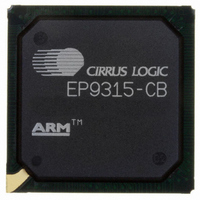
EP9315-CB Cirrus Logic Inc, EP9315-CB Datasheet - Page 742

EP9315-CB
Manufacturer Part Number
EP9315-CB
Description
IC ARM920T MCU 200MHZ 352-PBGA
Manufacturer
Cirrus Logic Inc
Series
EP9r
Specifications of EP9315-CB
Core Processor
ARM9
Core Size
16/32-Bit
Speed
200MHz
Connectivity
EBI/EMI, EIDE, Ethernet, I²C, IrDA, Keypad/Touchscreen, PCMCIA, SPI, UART/USART, USB
Peripherals
AC'97, DMA, I²:S, LCD, LED, MaverickKey, POR, PWM, WDT
Number Of I /o
16
Program Memory Type
ROMless
Ram Size
32K x 8
Voltage - Supply (vcc/vdd)
1.65 V ~ 3.6 V
Data Converters
A/D 8x12b
Oscillator Type
External
Operating Temperature
0°C ~ 70°C
Package / Case
352-BGA
Processor Series
EP93xx
Core
ARM920T
Data Bus Width
32 bit
3rd Party Development Tools
MDK-ARM, RL-ARM, ULINK2
Development Tools By Supplier
EDB9315A-Z
For Use With
598-1144 - KIT DEVELOPMENT EP9315 ARM9
Lead Free Status / RoHS Status
Contains lead / RoHS non-compliant
Eeprom Size
-
Program Memory Size
-
Lead Free Status / Rohs Status
No
Other names
598-1261
Available stocks
Company
Part Number
Manufacturer
Quantity
Price
Part Number:
EP9315-CBZ
Manufacturer:
CIRRUS
Quantity:
20 000
- Current page: 742 of 824
- Download datasheet (13Mb)
25
25-4
Analog Touch Screen Interface
EP93xx User’s Guide
25.2.1 Touch Screen Scanning: Four-wire and Eight-wire Operation
Figure 25-2
TSDetect, TSDischarge, TSXSample, and TSYSample are derived from the switch positions
in the diagram. These values are listed in
The left most part of the diagram shows how the switches are driven to detect a touch press.
This configuration is controlled by the TSDetect register.
The second part of the diagram shows all lines of the touch screen switched to ground for
discharging as controlled by the TSDischarge register.
The third example shows a voltage driven across the X-axis with the A / D sample input
connected to both Y-axis lines and the A / D referenced to the SX feedback lines as
controlled by the TSXSample register.
The right most part of the diagram shows a voltage driven across the Y-axis with the A / D
sample input connected to both X-axis lines and the A / D referenced to the SY feedback
lines for digitization as controlled by the TSYSample register.
Each time the analog switching configuration is changed, an appropriate time interval must
be provided for the circuit to stabilize due to the touch screen capacitance, and any EMI
filtering provided on the signals. This is controlled by the DLY field in the TSSetup register.
The analog touch screen interface circuitry is internally connected to a signed 12-bit analog-
to-digital converter. The 12-bit digital result is held stable until another sample is requested.
The controller reads the digital value by issuing a read pulse. This read pulse signal from the
controller is also used as a convert command for the analog-to-digital converter to begin
conversion of its next sample. The output of the ADC is a signed value. For the comparison
functions of the touch controller to work correctly, the TSSetup2.SIGND bit should be set.
The flow chart in
input on a touch screen. The ARM Core must load all of the setup registers for the touch
Table 25-1. Switch Definitions and Logical Safeguards to Prevent Physical Damage (Continued)
Bit 18
Bit 19
Bit 20
Bit 21
Bit 22
Bit 23
Bit 24
Bit 25
Bit 26
Bit 27
Bit 28
Bit 29
Bit 30
shows control for an 8-wire analog resistive touch screen. The register values
Figure 25-4
VBAT ADC input
TOUCH_PRES
S gate
DAC
sX+
sY+
sX-
sY-
sY-
X+
Y+
X+
Y+
Y-
demonstrates the sample process used for determining touch
Copyright 2007 Cirrus Logic
Pull-up to AVDD
Pull-up to AVDD
Load Resistor
Touch_Press
ADC REF+
ADC REF+
NAND gate
ADC REF-
ADC REF-
ADC input
AGND
AVDD
AVDD
AVDD
Table
SW19 = HIGH and SW11 = LOW and SW0 = LOW
SW20 = HIGH and SW13 = LOW and SW2 = LOW
SW21 = HIGH and SW14 = LOW and SW3 = LOW
25-2.
Also gates PRSTn for measuring battery with load
(SW0 = LOW or the bus SW[7-0] = 0x01)
(SW2 = LOW or the bus SW[7-0] = 0x04)
SW22 = HIGH and SW11 = LOW and
SW23 = HIGH and SW13 = LOW and
Gates input to prevent oscillations
DAC to ADC feedback test switch
-
-
-
-
-
DS785UM1
Related parts for EP9315-CB
Image
Part Number
Description
Manufacturer
Datasheet
Request
R

Part Number:
Description:
IC ARM9 SOC ENH UNIV 352PBGA
Manufacturer:
Cirrus Logic Inc
Datasheet:

Part Number:
Description:
32-Bit Microcontroller IC
Manufacturer:
Cirrus Logic Inc
Datasheet:

Part Number:
Description:
IC ARM920T MCU 200MHZ 352-PBGA
Manufacturer:
Cirrus Logic Inc
Datasheet:

Part Number:
Description:
MCU, MPU & DSP Development Tools Eval Bd Uni. ARM9 SOC Processor
Manufacturer:
Cirrus Logic Inc
Datasheet:

Part Number:
Description:
IC ARM920T MCU 166MHZ 208-LQFP
Manufacturer:
Cirrus Logic Inc
Datasheet:

Part Number:
Description:
IC ARM920T MCU 200MHZ 352-PBGA
Manufacturer:
Cirrus Logic Inc
Datasheet:

Part Number:
Description:
IC ARM920T MCU 166MHZ 208-LQFP
Manufacturer:
Cirrus Logic Inc
Datasheet:

Part Number:
Description:
Development Kit
Manufacturer:
Cirrus Logic Inc
Datasheet:

Part Number:
Description:
Development Kit
Manufacturer:
Cirrus Logic Inc
Datasheet:

Part Number:
Description:
High-efficiency PFC + Fluorescent Lamp Driver Reference Design
Manufacturer:
Cirrus Logic Inc
Datasheet:

Part Number:
Description:
Development Kit
Manufacturer:
Cirrus Logic Inc
Datasheet:

Part Number:
Description:
Development Kit
Manufacturer:
Cirrus Logic Inc
Datasheet:

Part Number:
Description:
Development Kit
Manufacturer:
Cirrus Logic Inc
Datasheet:

Part Number:
Description:
Ref Bd For Speakerbar MSA & DSP Products
Manufacturer:
Cirrus Logic Inc


