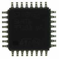
ST72F325K4T6 STMicroelectronics, ST72F325K4T6 Datasheet - Page 128

ST72F325K4T6
Manufacturer Part Number
ST72F325K4T6
Description
MCU 8BIT 16KB FLASH/ROM 32-LQFP
Manufacturer
STMicroelectronics
Series
ST7r
Datasheet
1.ST72F325K6T6.pdf
(197 pages)
Specifications of ST72F325K4T6
Core Processor
ST7
Core Size
8-Bit
Speed
8MHz
Connectivity
I²C, SCI, SPI
Peripherals
LVD, POR, PWM, WDT
Number Of I /o
24
Program Memory Size
16KB (16K x 8)
Program Memory Type
FLASH
Ram Size
512 x 8
Voltage - Supply (vcc/vdd)
3.8 V ~ 5.5 V
Data Converters
A/D 16x10b
Oscillator Type
Internal
Operating Temperature
-40°C ~ 85°C
Package / Case
32-LQFP
Processor Series
ST72F3x
Core
ST7
Data Bus Width
8 bit
Data Ram Size
512 B
Interface Type
I2C, SCI, SPI
Maximum Clock Frequency
8 MHz
Number Of Programmable I/os
48
Number Of Timers
2
Maximum Operating Temperature
+ 85 C
Mounting Style
SMD/SMT
Development Tools By Supplier
ST7232X-EVAL, ST7232X-SK/RAIS, ST72325-D/RAIS, ST7MDT20-DVP3, ST7MDT20J-EMU3, ST7MDT20M-EMU3, STX-RLINK
Minimum Operating Temperature
- 40 C
On-chip Adc
10 bit, 16 Channel
For Use With
497-5046 - KIT TOOL FOR ST7/UPSD/STR7 MCU
Lead Free Status / RoHS Status
Lead free / RoHS Compliant
Eeprom Size
-
Lead Free Status / Rohs Status
Details
Other names
497-5605
Available stocks
Company
Part Number
Manufacturer
Quantity
Price
Company:
Part Number:
ST72F325K4T6
Manufacturer:
ST
Quantity:
151
Company:
Part Number:
ST72F325K4T6
Manufacturer:
STMicroelectronics
Quantity:
10 000
Part Number:
ST72F325K4T6
Manufacturer:
ST
Quantity:
20 000
Company:
Part Number:
ST72F325K4T6TR
Manufacturer:
STMicroelectronics
Quantity:
10 000
ST72325xx
I
Bit 1 = M/SL Master/Slave.
This bit is set by hardware as soon as the interface
is in Master mode (writing START=1). It is cleared
by hardware after detecting a Stop condition on
the bus or a loss of arbitration (ARLO=1). It is also
cleared when the interface is disabled (PE=0).
0: Slave mode
1: Master mode
Bit 0 = SB Start bit (Master mode).
This bit is set by hardware as soon as the Start
condition
START=1). An interrupt is generated if ITE=1. It is
cleared by software reading SR1 register followed
by writing the address byte in DR register. It is also
cleared by hardware when the interface is disa-
bled (PE=0).
0: No Start condition
1: Start condition generated
I
Read Only
Reset Value: 0000 0000 (00h)
Bit 7:5 = Reserved. Forced to 0 by hardware.
Bit 4 = AF Acknowledge failure.
This bit is set by hardware when no acknowledge
is returned. An interrupt is generated if ITE=1. It is
cleared by software reading SR2 register or by
hardware when the interface is disabled (PE=0).
The SCL line is not held low while AF=1 but by oth-
er flags (SB or BTF) that are set at the same time.
0: No acknowledge failure
1: Acknowledge failure
Note:
– When an AF event occurs, the SCL line is not
Bit 3 = STOPF Stop detection (Slave mode).
This bit is set by hardware when a Stop condition
is detected on the bus after an acknowledge (if
ACK=1). An interrupt is generated if ITE=1. It is
cleared by software reading SR2 register or by
hardware when the interface is disabled (PE=0).
128/197
2
2
C BUS INTERFACE (Cont’d)
C STATUS REGISTER 2 (SR2)
held low; however, the SDA line can remain low
if the last bits transmitted are all 0. It is then nec-
essary to release both lines by software.
7
0
0
is
0
generated
AF
STOPF ARLO BERR GCAL
(following
a
write
0
The SCL line is not held low while STOPF=1.
0: No Stop condition detected
1: Stop condition detected
Bit 2 = ARLO Arbitration lost.
This bit is set by hardware when the interface los-
es the arbitration of the bus to another master. An
interrupt is generated if ITE=1. It is cleared by soft-
ware reading SR2 register or by hardware when
the interface is disabled (PE=0).
After an ARLO event the interface switches back
automatically to Slave mode (M/SL=0).
The SCL line is not held low while ARLO=1.
0: No arbitration lost detected
1: Arbitration lost detected
Note:
– In a Multimaster environment, when the interface
Bit 1 = BERR Bus error.
This bit is set by hardware when the interface de-
tects a misplaced Start or Stop condition. An inter-
rupt is generated if ITE=1. It is cleared by software
reading SR2 register or by hardware when the in-
terface is disabled (PE=0).
The SCL line is not held low while BERR=1.
0: No misplaced Start or Stop condition
1: Misplaced Start or Stop condition
Note:
– If a Bus Error occurs, a Stop or a repeated Start
Bit 0 = GCAL General Call (Slave mode).
This bit is set by hardware when a general call ad-
dress is detected on the bus while ENGC=1. It is
cleared by hardware detecting a Stop condition
(STOPF=1) or when the interface is disabled
(PE=0).
0: No general call address detected on bus
1: general call address detected on bus
is configured in Master Receive mode it does not
perform arbitration during the reception of the
Acknowledge Bit. Mishandling of the ARLO bit
from the I2CSR2 register may occur when a sec-
ond master simultaneously requests the same
data from the same slave and the I
does not acknowledge the data. The ARLO bit is
then left at 0 instead of being set.
condition should be generated by the Master to
re-synchronize communication, get the transmis-
sion acknowledged and the bus released for fur-
ther communication
2
C master


