MC908JL16CPE Freescale Semiconductor, MC908JL16CPE Datasheet - Page 128
MC908JL16CPE
Manufacturer Part Number
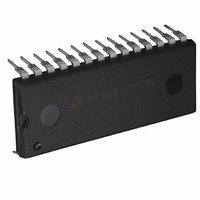
MC908JL16CPE
Description
IC MCU 16K FLASH 8MHZ 28-DIP
Manufacturer
Freescale Semiconductor
Series
HC08r
Datasheet
1.MC908JL16CFJER.pdf
(230 pages)
Specifications of MC908JL16CPE
Core Processor
HC08
Core Size
8-Bit
Speed
8MHz
Connectivity
I²C, SCI
Peripherals
LED, LVD, POR, PWM
Number Of I /o
23
Program Memory Size
16KB (16K x 8)
Program Memory Type
FLASH
Ram Size
512 x 8
Voltage - Supply (vcc/vdd)
2.7 V ~ 5.5 V
Data Converters
A/D 12x10b
Oscillator Type
Internal
Operating Temperature
-40°C ~ 85°C
Package / Case
28-DIP (0.600", 15.24mm)
Controller Family/series
HC08
No. Of I/o's
23
Ram Memory Size
512Byte
Cpu Speed
8MHz
No. Of Timers
2
Embedded Interface Type
I2C, SCI
Rohs Compliant
Yes
Processor Series
HC08JL
Core
HC08
Data Bus Width
8 bit
Data Ram Size
512 B
Interface Type
SCI
Maximum Clock Frequency
16 MHz
Number Of Programmable I/os
23
Number Of Timers
4
Operating Supply Voltage
2.7 V to 5.5 V
Maximum Operating Temperature
+ 85 C
Mounting Style
Through Hole
Development Tools By Supplier
FSICEBASE, DEMO908JL16E, M68CBL05CE
Minimum Operating Temperature
- 40 C
On-chip Adc
10 bit, 12 Channel
For Use With
DEMO908JL16E - BOARD DEMO FOR MC908JL16
Lead Free Status / RoHS Status
Lead free / RoHS Compliant
Eeprom Size
-
Lead Free Status / Rohs Status
Details
Available stocks
Company
Part Number
Manufacturer
Quantity
Price
Company:

Part Number:
MC908JL16CPE
Manufacturer:
AMS
Quantity:
183
Part Number:
MC908JL16CPE
Manufacturer:
FREESCALE
Quantity:
20 000


Analog-to-Digital Converter (ADC)
There are some situations where external system activity causes radiated or conducted noise emissions
or excessive V
in wait or I/O activity cannot be halted, the following recommendations may reduce the effect of noise on
the accuracy:
9.3.4.4 Code Width and Quantization Error
The ADC10 quantizes the ideal straight-line transfer function into 1024 steps (in 10-bit mode). Each step
ideally has the same height (1 code) and width. The width is defined as the delta between the transition
points from one code to the next. The ideal code width for an N bit converter (in this case N can be 8 or
10), defined as 1
Because of this quantization, there is an inherent quantization error. Because the converter performs a
conversion and then rounds to 8 or 10 bits, the code will transition when the voltage is at the midpoint
between the points where the straight line transfer function is exactly represented by the actual transfer
function. Therefore, the quantization error will be ± 1/2
however, the code width of the first ($000) conversion is only 1/2
or $3FF) is 1.5
9.3.4.5 Linearity Errors
The ADC10 may also exhibit non-linearity of several forms. Every effort has been made to reduce these
errors but the user should be aware of them because they affect overall accuracy. These errors are:
128
•
•
•
•
•
•
•
•
•
Place a 0.01 µF capacitor on the selected input channel to V
improve noise issues but will affect sample rate based on the external analog source resistance.
Operate the ADC10 in stop mode by setting ACLKEN, selecting the channel in ADCSC, and
executing a STOP instruction. This will reduce V
due to stop recovery.
Average the input by converting the output many times in succession and dividing the sum of the
results. Four samples are required to eliminate the effect of a 1
Reduce the effect of synchronous noise by operating off the asynchronous clock (ACLKEN=1) and
averaging. Noise that is synchronous to the ADCK cannot be averaged out.
Zero-Scale Error (E
the actual code width of the first conversion and the ideal code width (1/2
conversion is $001, then the difference between the actual $001 code width and its ideal (1
used.
Full-Scale Error (E
the last conversion and the ideal code width (1.5
difference between the actual $3FE code width and its ideal (1
Differential Non-Linearity (DNL) — This error is defined as the worst-case difference between the
actual code width and the ideal code width for all conversions.
Integral Non-Linearity (INL) — This error is defined as the highest-value the (absolute value of the)
running sum of DNL achieves. More simply, this is the worst-case difference of the actual transition
voltage to a given code and its corresponding ideal transition voltage, for all codes.
Total Unadjusted Error (TUE) — This error is defined as the difference between the actual transfer
function and the ideal straight-line transfer function, and therefore includes all forms of error.
DD
LSB
LSB
noise is coupled into the ADC10. In these cases, or when the MCU cannot be placed
.
, is:
FS
ZS
) — This error is defined as the difference between the actual code width of
) (sometimes called offset) — This error is defined as the difference between
MC68HC908JL16 Data Sheet, Rev. 1.1
1
LSB
= (V
REFH
–V
DD
LSB
LSB
REFL
noise but will increase effective conversion time
). Note, if the last conversion is $3FE, then the
in 8- or 10-bit mode. As a consequence,
) / 2
N
LSB
REFL
and the code width of the last ($FF
LSB
LSB
or V
) is used.
, one-time error.
SSA
LSB
(if available). This will
Freescale Semiconductor
). Note, if the first
LSB
) is
Related parts for MC908JL16CPE
Image
Part Number
Description
Manufacturer
Datasheet
Request
R

Part Number:
Description:
Manufacturer:
Freescale Semiconductor, Inc
Datasheet:
Part Number:
Description:
Manufacturer:
Freescale Semiconductor, Inc
Datasheet:
Part Number:
Description:
Manufacturer:
Freescale Semiconductor, Inc
Datasheet:
Part Number:
Description:
Manufacturer:
Freescale Semiconductor, Inc
Datasheet:
Part Number:
Description:
Manufacturer:
Freescale Semiconductor, Inc
Datasheet:
Part Number:
Description:
Manufacturer:
Freescale Semiconductor, Inc
Datasheet:
Part Number:
Description:
Manufacturer:
Freescale Semiconductor, Inc
Datasheet:
Part Number:
Description:
Manufacturer:
Freescale Semiconductor, Inc
Datasheet:
Part Number:
Description:
Manufacturer:
Freescale Semiconductor, Inc
Datasheet:
Part Number:
Description:
Manufacturer:
Freescale Semiconductor, Inc
Datasheet:
Part Number:
Description:
Manufacturer:
Freescale Semiconductor, Inc
Datasheet:
Part Number:
Description:
Manufacturer:
Freescale Semiconductor, Inc
Datasheet:
Part Number:
Description:
Manufacturer:
Freescale Semiconductor, Inc
Datasheet:
Part Number:
Description:
Manufacturer:
Freescale Semiconductor, Inc
Datasheet:
Part Number:
Description:
Manufacturer:
Freescale Semiconductor, Inc
Datasheet: