ST72F262G2B5 STMicroelectronics, ST72F262G2B5 Datasheet - Page 31
ST72F262G2B5
Manufacturer Part Number
ST72F262G2B5
Description
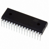
IC MCU 8BIT 8K FLASH 32-SDIP
Manufacturer
STMicroelectronics
Series
ST7r
Datasheet
1.STEVAL-ISQ002V1.pdf
(172 pages)
Specifications of ST72F262G2B5
Core Processor
ST7
Core Size
8-Bit
Speed
16MHz
Connectivity
SPI
Peripherals
LVD, POR, PWM, WDT
Number Of I /o
22
Program Memory Size
8KB (8K x 8)
Program Memory Type
FLASH
Ram Size
256 x 8
Voltage - Supply (vcc/vdd)
2.7 V ~ 5.5 V
Data Converters
A/D 6x10b
Oscillator Type
Internal
Operating Temperature
-10°C ~ 85°C
Package / Case
32-SDIP (0.400", 10.16mm)
Processor Series
ST72F2x
Core
ST7
Data Bus Width
8 bit
Data Ram Size
256 B
Interface Type
I2C, SCI, SPI
Maximum Clock Frequency
8 MHz
Number Of Programmable I/os
22
Number Of Timers
16 bit
Maximum Operating Temperature
+ 85 C
Mounting Style
Through Hole
Development Tools By Supplier
ST7F264-IND/USB, ST72F34X-SK/RAIS, ST7MDT10-DVP3, ST7MDT10-EMU3, STX-RLINK
Minimum Operating Temperature
- 40 C
On-chip Adc
8 bit
Lead Free Status / RoHS Status
Lead free / RoHS Compliant
Eeprom Size
-
Lead Free Status / Rohs Status
Details
Available stocks
Company
Part Number
Manufacturer
Quantity
Price
Company:

Part Number:
ST72F262G2B5
Manufacturer:
TAIYO
Quantity:
8 122


INTERRUPTS (Cont’d)
7.5 INTERRUPT REGISTER DESCRIPTION
CPU CC REGISTER INTERRUPT BITS
Read/Write
Reset Value: 111x 1010 (xAh)
Bit 5, 3 = I1, I0 Software Interrupt Priority
These two bits indicate the current interrupt soft-
ware priority.
These two bits are set/cleared by hardware when
entering in interrupt. The loaded value is given by
the corresponding bits in the interrupt software pri-
ority registers (ISPRx).
They can be also set/cleared by software with the
RIM, SIM, HALT, WFI, IRET and PUSH/POP in-
structions (see “Interrupt Dedicated Instruction
Set” table).
*Note: TRAP and RESET events are non maska-
ble sources and can interrupt a level 3 program.
Level 0 (main)
Level 1
Level 2
Level 3 (= interrupt disable*)
Interrupt Software Priority
7
1
1
I1
H
I0
Level
High
Low
N
I1
1
0
0
1
Z
I0
0
1
0
1
C
0
INTERRUPT SOFTWARE PRIORITY REGIS-
TERS (ISPRX)
Read/Write (bits 7:4 of ISPR3 are read only)
Reset Value: 1111 1111 (FFh)
These four registers contain the interrupt software
priority of each interrupt vector.
– Each interrupt vector (except RESET and TRAP)
– Each I1_x and I0_x bit value in the ISPRx regis-
– Level 0 can not be written (I1_x=1, I0_x=0). In
The RESET and TRAP vectors have no software
priorities. When one is serviced, the I1 and I0 bits
of the CC register are both set.
Caution: If the I1_x and I0_x bits are modified
while the interrupt x is executed the following be-
haviour has to be considered: If the interrupt x is
still pending (new interrupt or flag not cleared) and
the new software priority is higher than the previ-
ous one, the interrupt x is re-entered. Otherwise,
the software priority stays unchanged up to the
next interrupt request (after the IRET of the inter-
rupt x).
has corresponding bits in these registers where
its own software priority is stored. This corre-
spondance is shown in the following table.
ters has the same meaning as the I1 and I0 bits
in the CC register.
this case, the previously stored value is kept. (ex-
ample: previous=CFh, write=64h, result=44h)
ISPR0
ISPR1
ISPR2
ISPR3
Vector Address
FFFBh-FFFAh
ST72260Gx, ST72262Gx, ST72264Gx
FFE1h-FFE0h
FFF9h-FFF8h
I1_11 I0_11 I1_10 I0_10 I1_9
I1_3
I1_7
7
1
...
I0_3
I0_7
1
I1_2
I1_6
1
I0_2
I0_6
1
I1_13 I0_13 I1_12 I0_12
I1_1
I1_5
ISPRx Bits
Not used
I0_1
I0_5
I0_9
ei0
ei1
...
I1_0
I1_4
I1_8
31/172
I0_0
I0_4
I0_8
0
Related parts for ST72F262G2B5
Image
Part Number
Description
Manufacturer
Datasheet
Request
R

Part Number:
Description:
STMicroelectronics [RIPPLE-CARRY BINARY COUNTER/DIVIDERS]
Manufacturer:
STMicroelectronics
Datasheet:
Part Number:
Description:
STMicroelectronics [LIQUID-CRYSTAL DISPLAY DRIVERS]
Manufacturer:
STMicroelectronics
Datasheet:

Part Number:
Description:
BOARD EVAL FOR MEMS SENSORS
Manufacturer:
STMicroelectronics
Datasheet:
Part Number:
Description:
NPN TRANSISTOR POWER MODULE
Manufacturer:
STMicroelectronics
Datasheet:
Part Number:
Description:
TURBOSWITCH ULTRA-FAST HIGH VOLTAGE DIODE
Manufacturer:
STMicroelectronics
Datasheet:
Part Number:
Description:
Manufacturer:
STMicroelectronics
Datasheet:
Part Number:
Description:
DIODE / SCR MODULE
Manufacturer:
STMicroelectronics
Datasheet:
Part Number:
Description:
DIODE / SCR MODULE
Manufacturer:
STMicroelectronics
Datasheet:
Part Number:
Description:
Search -----> STE16N100
Manufacturer:
STMicroelectronics
Datasheet:
Part Number:
Description:
Search ---> STE53NA50
Manufacturer:
STMicroelectronics
Datasheet:
Part Number:
Description:
NPN Transistor Power Module
Manufacturer:
STMicroelectronics
Datasheet:
Part Number:
Description:
DIODE / SCR MODULE
Manufacturer:
STMicroelectronics
Datasheet: