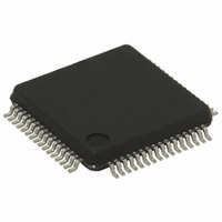
ST72F321BAR7T6 STMicroelectronics, ST72F321BAR7T6 Datasheet - Page 59

ST72F321BAR7T6
Manufacturer Part Number
ST72F321BAR7T6
Description
IC MCU 8BIT 48KB FLASH 64-LQFP
Manufacturer
STMicroelectronics
Series
ST7r
Datasheet
1.ST72F321BK6T6.pdf
(187 pages)
Specifications of ST72F321BAR7T6
Core Processor
ST7
Core Size
8-Bit
Speed
8MHz
Connectivity
I²C, SCI, SPI
Peripherals
LVD, POR, PWM, WDT
Number Of I /o
48
Program Memory Size
48KB (48K x 8)
Program Memory Type
FLASH
Ram Size
1.5K x 8
Voltage - Supply (vcc/vdd)
3.8 V ~ 5.5 V
Data Converters
A/D 16x10b
Oscillator Type
Internal
Operating Temperature
-40°C ~ 85°C
Package / Case
64-LQFP
Processor Series
ST72F3x
Core
ST7
Data Bus Width
8 bit
Data Ram Size
1.5 KB
Interface Type
I2C, SCI, SPI
Maximum Clock Frequency
8 MHz
Number Of Programmable I/os
48
Number Of Timers
2
Maximum Operating Temperature
+ 85 C
Mounting Style
SMD/SMT
Development Tools By Supplier
ST7232X-EVAL, ST7232X-SK/RAIS, ST72321B-D/RAIS, ST7MDT20-DVP3, ST7MDT20J-EMU3, ST7MDT20M-EMU3, STX-RLINK
Minimum Operating Temperature
- 40 C
On-chip Adc
10 bit, 16 Channel
Lead Free Status / RoHS Status
Lead free / RoHS Compliant
Eeprom Size
-
Lead Free Status / Rohs Status
Details
Available stocks
Company
Part Number
Manufacturer
Quantity
Price
Company:
Part Number:
ST72F321BAR7T6
Manufacturer:
ST
Quantity:
1 600
Company:
Part Number:
ST72F321BAR7T6
Manufacturer:
STMicroelectronics
Quantity:
10 000
Part Number:
ST72F321BAR7T6
Manufacturer:
ST
Quantity:
20 000
MAIN CLOCK CONTROLLER WITH REAL TIME CLOCK (Cont’d)
Bit 0 = OIF Oscillator interrupt flag
This bit is set by hardware and cleared by software
reading the MCCSR register. It indicates when set
that the main oscillator has reached the selected
elapsed time (TB1:0).
0: Timeout not reached
1: Timeout reached
CAUTION: The BRES and BSET instructions
must not be used on the MCCSR register to avoid
unintentionally clearing the OIF bit.
Table 15. Main Clock Controller Register Map and Reset Values
Address
002Dh
(Hex.)
002Ch
002Bh
SICSR
Reset Value
MCCSR
Reset Value
MCCBCR
Reset Value
Register
Label
AVDS
MCO
7
0
0
0
AVDIE
CP1
ST72321BRx, ST72321BARx ST72321BJx, ST72321BKx
6
0
0
0
AVDF
CP0
5
0
0
0
MCC BEEP CONTROL REGISTER (MCCBCR)
Read/Write
Reset Value: 0000 0000 (00h)
Bit 7:2 = Reserved, must be kept cleared.
Bit 1:0 = BC[1:0] Beep control
These 2 bits select the PF1 pin beep capability.
The beep output signal is available in ACTIVE-
HALT mode but has to be disabled to reduce the
consumption.
LVDRF
BC1
7
0
SMS
0
0
1
1
4
0
0
x
0
BC0
0
1
0
1
TB1
3
0
0
0
0
Beep mode with f
0
~500-Hz
~1-KHz
~2-KHz
TB0
2
0
0
0
0
Off
BC1
OIE
0
~50% duty cycle
1
0
0
0
OSC2
Beep signal
BC1
Output
=8MHz
WDGRF
BC0
OIF
59/187
0
x
0
0
BC0
0


