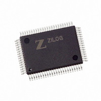
Z16F2810FI20EG Zilog, Z16F2810FI20EG Datasheet - Page 246

Z16F2810FI20EG
Manufacturer Part Number
Z16F2810FI20EG
Description
IC ZNEO MCU FLASH 128K 80QFP
Manufacturer
Zilog
Series
Encore!® ZNEOr
Datasheet
1.Z16F2800100ZCOG.pdf
(388 pages)
Specifications of Z16F2810FI20EG
Core Processor
ZNEO
Core Size
16-Bit
Speed
20MHz
Connectivity
I²C, IrDA, LIN, SPI, UART/USART
Peripherals
Brown-out Detect/Reset, DMA, POR, PWM, WDT
Number Of I /o
60
Program Memory Size
128KB (128K x 8)
Program Memory Type
FLASH
Ram Size
4K x 8
Voltage - Supply (vcc/vdd)
2.7 V ~ 3.6 V
Data Converters
A/D 12x10b
Oscillator Type
Internal
Operating Temperature
-40°C ~ 105°C
Package / Case
80-BQFP
Data Bus Width
16 bit
Data Ram Size
4 B
Interface Type
ESPI, I2C, UART
Maximum Clock Frequency
20 MHz
Number Of Programmable I/os
60
Number Of Timers
4
Operating Supply Voltage
2.7 V to 3.6 V
Maximum Operating Temperature
+ 105 C
Mounting Style
SMD/SMT
Minimum Operating Temperature
- 40 C
On-chip Adc
10 bit, 12 Channel
For Use With
770-1003 - ISP 4PORT FOR ZILOG ZNEO MCU269-4537 - DEV KIT FOR Z16F ZNEO
Lead Free Status / RoHS Status
Lead free / RoHS Compliant
Eeprom Size
-
Lead Free Status / Rohs Status
Details
Available stocks
Company
Part Number
Manufacturer
Quantity
Price
- Current page: 246 of 388
- Download datasheet (22Mb)
Table 111. I
.
:
BITS
FIELD
RESET
R/W
ADDR
PS022008-0810
Note:
I
2
C Baud Rate High and Low Byte Registers
2
C Baud Rate High Byte Register (I2CBRH)
7
TXI—Enable TDRE interrupts
This bit enables interrupts when the I
NAK—Send NAK
Setting this bit sends a Not Acknowledge condition after the next byte of data has been
received. It is automatically deasserted after the Not Acknowledge is sent or the IEN bit is
cleared. If this bit is 1, it cannot be cleared to 0 by writing to the register.
FLUSH—Flush Data
Setting this bit clears the I
flushing of the I
byte has been written to the I
FILTEN—I
Setting this bit enables low-pass digital filters on the SDA and SCL input signals. This
function provides the spike suppression filter required in I2C Fast Mode. These filters
reject any input pulse with periods less than a full system clock cycle. The filters introduce
a 3-system clock cycle latency on the inputs.
The I
page 231) combine to form a 16-bit reload value,
Generator.
The baud rate High and Low Byte Registers must be programmed for the I
slave mode as well as in master mode. In slave mode, the baud rate value programmed
must match the master's baud rate within +/- 25% for proper operation.
The I
If
I2C Baud Rate (bps)
BRG
2
2
C Baud Rate High and Low Byte registers (see
C baud rate is calculated using the below equation.
=
0000H
6
2
C Signal Filter Enable
2
, use
C Data register when an NAK condition is received after the next data
10000H
5
2
=
P R E L I M I N A R Y
C Data register and sets the
2
System Clock Frequency (Hz)
--------------------------------------------------------------------------- -
C Data register. Reading this bit always returns 0.
in the equation.
4
FF-E243H
2
C Data register is empty.
4 BRG[15:0]
BRH
FFH
R/W
3
BRG
Table 111
[15:0], for the I
TDRE
2
bit to 1. This bit allows
I
2
C Master/Slave Controller
and
Product Specification
ZNEO
Table 112
2
C Baud Rate
1
2
C baud rate in
Z16F Series
on
0
230
Related parts for Z16F2810FI20EG
Image
Part Number
Description
Manufacturer
Datasheet
Request
R

Part Number:
Description:
Communication Controllers, ZILOG INTELLIGENT PERIPHERAL CONTROLLER (ZIP)
Manufacturer:
Zilog, Inc.
Datasheet:

Part Number:
Description:
KIT DEV FOR Z8 ENCORE 16K TO 64K
Manufacturer:
Zilog
Datasheet:

Part Number:
Description:
KIT DEV Z8 ENCORE XP 28-PIN
Manufacturer:
Zilog
Datasheet:

Part Number:
Description:
DEV KIT FOR Z8 ENCORE 8K/4K
Manufacturer:
Zilog
Datasheet:

Part Number:
Description:
KIT DEV Z8 ENCORE XP 28-PIN
Manufacturer:
Zilog
Datasheet:

Part Number:
Description:
DEV KIT FOR Z8 ENCORE 4K TO 8K
Manufacturer:
Zilog
Datasheet:

Part Number:
Description:
CMOS Z8 microcontroller. ROM 16 Kbytes, RAM 256 bytes, speed 16 MHz, 32 lines I/O, 3.0V to 5.5V
Manufacturer:
Zilog, Inc.
Datasheet:

Part Number:
Description:
Low-cost microcontroller. 512 bytes ROM, 61 bytes RAM, 8 MHz
Manufacturer:
Zilog, Inc.
Datasheet:

Part Number:
Description:
Z8 4K OTP Microcontroller
Manufacturer:
Zilog, Inc.
Datasheet:

Part Number:
Description:
CMOS SUPER8 ROMLESS MCU
Manufacturer:
Zilog, Inc.
Datasheet:

Part Number:
Description:
SL1866 CMOSZ8 OTP Microcontroller
Manufacturer:
Zilog, Inc.
Datasheet:

Part Number:
Description:
SL1866 CMOSZ8 OTP Microcontroller
Manufacturer:
Zilog, Inc.
Datasheet:

Part Number:
Description:
OTP (KB) = 1, RAM = 125, Speed = 12, I/O = 14, 8-bit Timers = 2, Comm Interfaces Other Features = Por, LV Protect, Voltage = 4.5-5.5V
Manufacturer:
Zilog, Inc.
Datasheet:

Part Number:
Description:
Manufacturer:
Zilog, Inc.
Datasheet:


