MC9S08JM8CLC Freescale Semiconductor, MC9S08JM8CLC Datasheet - Page 207
MC9S08JM8CLC
Manufacturer Part Number
MC9S08JM8CLC
Description
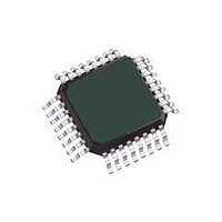
MCU 8BIT 8K FLASH 32-LQFP
Manufacturer
Freescale Semiconductor
Series
HCS08r
Datasheet
1.DEMO9S08JM16.pdf
(386 pages)
Specifications of MC9S08JM8CLC
Core Processor
HCS08
Core Size
8-Bit
Speed
48MHz
Connectivity
I²C, LIN, SCI, SPI, USB
Peripherals
LVD, POR, PWM, WDT
Number Of I /o
21
Program Memory Size
8KB (8K x 8)
Program Memory Type
FLASH
Ram Size
1K x 8
Voltage - Supply (vcc/vdd)
2.7 V ~ 5.5 V
Data Converters
A/D 4x12b
Oscillator Type
External
Operating Temperature
-40°C ~ 85°C
Package / Case
32-LQFP
Processor Series
S08JM
Core
HCS08
Data Bus Width
8 bit
Data Ram Size
1 KB
Interface Type
I2C, SPI
Maximum Clock Frequency
48 MHz
Number Of Programmable I/os
37
Number Of Timers
2
Operating Supply Voltage
2.7 V to 5.5 V
Maximum Operating Temperature
+ 85 C
Mounting Style
SMD/SMT
3rd Party Development Tools
EWS08
Development Tools By Supplier
DEMOJM, DEMOJMSKT, DEMOFLEXISJMSD, DEMO9S08JM16
Minimum Operating Temperature
- 40 C
On-chip Adc
12 bit, 4 Channel
Controller Family/series
HCS08
No. Of I/o's
21
Ram Memory Size
1KB
Cpu Speed
48MHz
No. Of Timers
2
Digital Ic Case Style
LQFP
Rohs Compliant
Yes
Lead Free Status / RoHS Status
Lead free / RoHS Compliant
Eeprom Size
-
Lead Free Status / Rohs Status
Lead free / RoHS Compliant


In this particular case, the MCU has been attached to a PCB and the entire assembly is undergoing final
test with automated test equipment. A separate signal or message is provided to the MCU operating under
user provided software control. The MCU initiates a trim procedure as outlined in
tester supplies a precision reference signal.
If the intended bus frequency is near the maximum allowed for the device, it is recommended to trim using
a reference divider value (RDIV setting) of twice the final value. After the trim procedure is complete, the
reference divider can be restored. This will prevent accidental overshoot of the maximum clock frequency.
Freescale Semiconductor
Initial conditions:
1) Clock supplied from ATE has 500 μs duty period
2) MCG configured for internal reference with 8MHz bus
INCREASES THE FREQUENCY)
(DECREASING TRMVAL
TRMVAL - 256/ (2**n)
COUNT < EXPECTED = 500
(RUNNING TOO SLOW)
TRMVAL =
n = n + 1
IS n > 9?
MC9S08JM16 Series Data Sheet, Rev. 2
(COUNT = # OF BUS CLOCKS / 8)
DECREASES THE FREQUENCY)
Figure 12-13. Trim Procedure
NO
START TRIM PROCEDURE
INCOMING CLOCK WIDTH
(INCREASING TRMVAL
TRMVAL + 256/ (2**n)
TRMVAL = $100
CASE STATEMENT
TRMVAL =
MEASURE
YES
n=1
.
COUNT > EXPECTED = 500
(RUNNING TOO FAST)
COUNT = EXPECTED = 500
Multi-Purpose Clock Generator (S08MCGV1)
Figure 12-13
NON-VOLATILE MEMORY
STORE MCGTRM AND
FTRIM VALUES IN
CONTINUE
while the
207
Related parts for MC9S08JM8CLC
Image
Part Number
Description
Manufacturer
Datasheet
Request
R

Part Number:
Description:
Manufacturer:
Freescale Semiconductor, Inc
Datasheet:
Part Number:
Description:
Manufacturer:
Freescale Semiconductor, Inc
Datasheet:
Part Number:
Description:
Manufacturer:
Freescale Semiconductor, Inc
Datasheet:
Part Number:
Description:
Manufacturer:
Freescale Semiconductor, Inc
Datasheet:
Part Number:
Description:
Manufacturer:
Freescale Semiconductor, Inc
Datasheet:
Part Number:
Description:
Manufacturer:
Freescale Semiconductor, Inc
Datasheet:
Part Number:
Description:
Manufacturer:
Freescale Semiconductor, Inc
Datasheet:
Part Number:
Description:
Manufacturer:
Freescale Semiconductor, Inc
Datasheet:
Part Number:
Description:
Manufacturer:
Freescale Semiconductor, Inc
Datasheet:
Part Number:
Description:
Manufacturer:
Freescale Semiconductor, Inc
Datasheet:
Part Number:
Description:
Manufacturer:
Freescale Semiconductor, Inc
Datasheet:
Part Number:
Description:
Manufacturer:
Freescale Semiconductor, Inc
Datasheet:
Part Number:
Description:
Manufacturer:
Freescale Semiconductor, Inc
Datasheet:
Part Number:
Description:
Manufacturer:
Freescale Semiconductor, Inc
Datasheet:
Part Number:
Description:
Manufacturer:
Freescale Semiconductor, Inc
Datasheet: