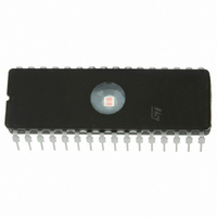
ST7FMC1K2B6 STMicroelectronics, ST7FMC1K2B6 Datasheet - Page 34

ST7FMC1K2B6
Manufacturer Part Number
ST7FMC1K2B6
Description
MCU 8BIT 8K FLASH 32DIP
Manufacturer
STMicroelectronics
Series
ST7r
Datasheet
1.ST7FMC2S4T6.pdf
(309 pages)
Specifications of ST7FMC1K2B6
Core Processor
ST7
Core Size
8-Bit
Speed
8MHz
Connectivity
LINSCI
Peripherals
LVD, Motor Control PWM, POR, PWM, WDT
Number Of I /o
17
Program Memory Size
8KB (8K x 8)
Program Memory Type
FLASH
Ram Size
384 x 8
Voltage - Supply (vcc/vdd)
3.8 V ~ 5.5 V
Data Converters
A/D 16x10b
Oscillator Type
Internal
Operating Temperature
-40°C ~ 85°C
Package / Case
32-DIP (0.600", 15.24mm)
For Use With
497-8402 - BOARD EVAL COMPLETE INVERTER497-8400 - KIT IGBT PWR MODULE CTRL ST7MC497-4734 - EVAL KIT 3KW POWER DRIVER BOARD497-4733 - EVAL KIT 1KW POWER DRIVER BOARD497-4732 - EVAL KIT 300W POWER DRIVER BOARD497-4731 - EVAL KIT PWR DRIVER CONTROL BRD
Lead Free Status / RoHS Status
Lead free / RoHS Compliant
Eeprom Size
-
Other names
497-4864
- Current page: 34 of 309
- Download datasheet (6Mb)
ST7MC1xx/ST7MC2xx
SYSTEM INTEGRITY MANAGEMENT (Cont’d)
6.3.3 Clock Security System (CSS)
The Clock Security System (CSS) protects the
ST7 against main clock problems. To allow the in-
tegration of the security features in the applica-
tions, it is based on a PLL which can provide a
backup clock. The PLL can be enabled or disabled
by option byte or by software. It requires an 8-MHz
input clock and provides a 16-MHz output clock.
6.3.3.1 Safe Oscillator Control
The safe oscillator of the CSS block is made of a
PLL.
If the clock signal disappears (due to a broken or
disconnected resonator...) the PLL continues to
provide a lower frequency, which allows the ST7 to
perform some rescue operations.
Note: The clock signal must be present at start-up.
Otherwise, the ST7MC will not start and will be
maintained in RESET conditions.
6.3.3.2 Limitation detection
The automatic safe oscillator selection is notified
by hardware setting the CSSD bit of the SICSR
register. An interrupt can be generated if the CS-
SIE bit has been previously set.
These two bits are described in the SICSR register
description.
34/309
1
6.3.4 Low Power Modes
6.3.4.1 Interrupts
The CSS or AVD interrupt events generate an in-
terrupt if the corresponding Enable Control Bit
(CSSIE or AVDIE) is set and the interrupt mask in
the CC register is reset (RIM instruction).
Note 1: This interrupt allows to exit from Active-
halt mode.
Wait
Halt
CSS event detection
(safe oscillator acti-
vated as main clock)
AVD event
Mode
Interrupt Event
No effect on SI. CSS and AVD interrupts
cause the device to exit from Wait mode.
The CRSR register is frozen.
The CSS (including the safe oscillator) is
disabled until Halt mode is exited. The pre-
vious CSS configuration resumes when the
MCU is woken up by an interrupt with “exit
from Halt mode” capability or from the coun-
ter reset value when the MCU is woken up
by a RESET. The AVD remains active, and
an AVD interrupt can be used to exit from
Halt mode.
CSSD
Event
AVDF
Flag
Description
Control
Enable
AVDIE
CSSIE
Bit
from
Wait
Exit
Yes
Yes
from
No
Exit
Halt
Yes
1)
Related parts for ST7FMC1K2B6
Image
Part Number
Description
Manufacturer
Datasheet
Request
R

Part Number:
Description:
STMicroelectronics [RIPPLE-CARRY BINARY COUNTER/DIVIDERS]
Manufacturer:
STMicroelectronics
Datasheet:

Part Number:
Description:
STMicroelectronics [LIQUID-CRYSTAL DISPLAY DRIVERS]
Manufacturer:
STMicroelectronics
Datasheet:

Part Number:
Description:
BOARD EVAL FOR MEMS SENSORS
Manufacturer:
STMicroelectronics
Datasheet:

Part Number:
Description:
NPN TRANSISTOR POWER MODULE
Manufacturer:
STMicroelectronics
Datasheet:

Part Number:
Description:
TURBOSWITCH ULTRA-FAST HIGH VOLTAGE DIODE
Manufacturer:
STMicroelectronics
Datasheet:

Part Number:
Description:
Manufacturer:
STMicroelectronics
Datasheet:

Part Number:
Description:
DIODE / SCR MODULE
Manufacturer:
STMicroelectronics
Datasheet:

Part Number:
Description:
DIODE / SCR MODULE
Manufacturer:
STMicroelectronics
Datasheet:

Part Number:
Description:
Search -----> STE16N100
Manufacturer:
STMicroelectronics
Datasheet:

Part Number:
Description:
Search ---> STE53NA50
Manufacturer:
STMicroelectronics
Datasheet:

Part Number:
Description:
NPN Transistor Power Module
Manufacturer:
STMicroelectronics
Datasheet:

Part Number:
Description:
DIODE / SCR MODULE
Manufacturer:
STMicroelectronics
Datasheet:


