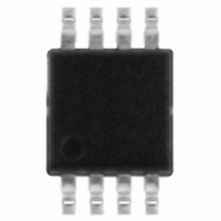
TSV912AIST STMicroelectronics, TSV912AIST Datasheet - Page 9

TSV912AIST
Manufacturer Part Number
TSV912AIST
Description
IC OPAMP R-R I/O DUAL 8MHZ 8MSOP
Manufacturer
STMicroelectronics
Datasheet
1.TSV911ILT.pdf
(20 pages)
Specifications of TSV912AIST
Amplifier Type
General Purpose
Number Of Circuits
2
Output Type
Rail-to-Rail
Slew Rate
4.5 V/µs
Gain Bandwidth Product
8MHz
Current - Input Bias
1pA
Current - Supply
820µA
Current - Output / Channel
35mA
Voltage - Supply, Single/dual (±)
2.5 V ~ 5.5 V
Operating Temperature
-40°C ~ 125°C
Mounting Type
Surface Mount
Package / Case
8-MSOP, Micro8™, 8-uMAX, 8-uSOP,
Number Of Channels
2
Voltage Gain Db
91 dB
Common Mode Rejection Ratio (min)
62 dB
Input Offset Voltage
1.5 mV
Operating Supply Voltage
3 V, 5 V
Supply Current
2.2 mA
Maximum Operating Temperature
+ 125 C
Mounting Style
SMD/SMT
Minimum Operating Temperature
- 40 C
Lead Free Status / RoHS Status
Lead free / RoHS Compliant
-3db Bandwidth
-
Voltage - Input Offset
-
Lead Free Status / Rohs Status
Details
Other names
497-5830-2
Available stocks
Company
Part Number
Manufacturer
Quantity
Price
Part Number:
TSV912AIST
Manufacturer:
ST
Quantity:
20 000
TSV91x
Figure 7.
Figure 9.
Figure 11. Positive slew rate
− 10
− 10
− 20
− 20
− 30
− 30
− 40
− 40
40
40
30
30
20
20
10
10
0 0
6 6
5 5
4 4
3 3
2 2
1 1
0 0
2.5
2.5
Vcc=2.5V, Vicm=0.5V
Cl=100pF, Rl=2kOhms, Vrl=Vcc/2
Tamb=25°C
Voltage gain and phase vs.
frequency at V
V
Phase margin vs. capacitive load
Vin : from 0.5V to Vcc-0.5V
SR : calculated from 10% to 90%
icm
3.0
3.0
Vcc=5V, Rl=2kOhms
Vrl=2.5V
Tamb=25°C
10
= 0.5 V
6
3.5
3.5
Supply Voltage (V)
4.0
4.0
CC
= 2.5 V and
10
4.5
4.5
7
5.0
5.0
Doc ID 12584 Rev 7
5.5
5.5
160
120
80
40
0
− 40
− 80
− 120
− 160
Figure 8.
Figure 10. Phase margin vs. output current
Figure 12. Negative slew rate
-10
-10
-20
-20
-30
-30
-40
-40
40
40
30
30
20
20
10
10
0 0
80
80
70
70
60
60
50
50
40
40
30
30
20
20
10
10
0 0
-6 -6
-5 -5
-4 -4
-3 -3
-2 -2
-1 -1
0 0
2.5
− 20
− 20
Vcc=5V, Cl=100pF
Tamb=25°C
Voltage gain and phase vs.
frequency at V
V
icm
Vin : from 0.5V to Vcc-0.5V
SR : calculated from 10% to 90%
3.0
3.0
10
= 0.5 V
6
− 10
− 10
3.5
Electrical characteristics
4.0
0 0
CC
= 5.5 V and
10
4.5
Phase
7
10
10
5.0
5.0
20
20
5.5
9/20


